question about transistor design

Thread Starter

samy555

Joined May 24, 2010
116
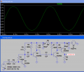
I often see many electronic circuits using a simple fixed biased common emmiter transistor like Q2 in the following
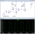
and transistor T3 here:
Why those designers didn't use a more strong configurations like voltage divider or collector feedback? Thank you very much
 

nsaspook

Joined Aug 27, 2009
16,359
Sometimes you just need a gain stage where the exact bias is not critical because the signal is low-level. With collector feedback you also get a increase in input impedance that's needed for a condenser mic input stage.
T3 is a RF amp stage that looks to be class AB so the input bias on it is a function of the drive signal from T2 and the R7 quiescent bias is to have it operate in a more linear part of the collector current curve during small audio signal modulation to reduce harmonic distortion.
 

Thread Starter

samy555

Joined May 24, 2010
116
T3 is a RF amp stage that looks to be class AB so the input bias on it is a function of the drive signal from T2 and the R7 quiescent bias is to have it operate in a more linear part of the collector current curve during small audio signal modulation to reduce harmonic distortion.
I think that class AB uses two transistors please explain thank you
 

Audioguru

Joined Dec 20, 2007
11,248
With collector feedback you also get a increase in input impedance that's needed for a condenser mic input stage.
Sorry but you are wrong. The feedback reduces the input impedance of the transistor.
The mic is NOT a condenser type, it is an electret type.

T3 is a RF amp stage that looks to be class AB so the input bias on it is a function of the drive signal from T2 and the R7 quiescent bias is to have it operate in a more linear part of the collector current curve during small audio signal modulation to reduce harmonic distortion.
No.
The RF transistor has class A bias. It might be almost cutoff or almost saturated so the tuned LC circuit at its collector keeps the waveform linear.
 

Thread Starter

samy555

Joined May 24, 2010
116
Thank you Audioguru
That was a high-value answer
But you did not answer my question which is:
Why do designers use this weak configuration and it operate well in their designs and not using a strong voltage divider one?

thank you very much
 

Ron H

Joined Apr 14, 2005
7,063
I think Q2 is intended to be a limiter, i.e., the transistor is driven from saturation to cutoff. It doesn't need typical "linear" amplifier stage biasing.
 

Attachments

Audioguru

Joined Dec 20, 2007
11,248
Why do designers use this weak configuration and it operates well in their designs and do not use a strong voltage divider one?
I showed you that some BC547 transistors will work, some will be cutoff and will not work and others will be saturated and also will not work.

Why do you say the lousy design works well?
 

nsaspook

Joined Aug 27, 2009
16,359
I think Q2 is intended to be a limiter, i.e., the transistor is driven from saturation to cutoff. It doesn't need typical "linear" amplifier stage biasing.
The first circuit looks to be a small speaker or headphone driver (something with a coil) so I hope it's not a limiter at the mic's normal input levels. :)
 

nsaspook

Joined Aug 27, 2009
16,359
Which reduces the input impedance. The 1Meg resistor looks ≈like 1Meg/Av.
You can't use the static 1M resistor to calculate that. The input impedance is determined by the transistor Zin.
http://en.wikipedia.org/wiki/Negative_feedback_amplifier#Input_and_output_resistances

In the case of the voltage amplifier, the output voltage βVout of the feedback network is applied in series and with an opposite polarity to the input voltage Vx travelling over the loop (but in respect to ground, the polarities are the same). As a result, the effective voltage across and the current through the amplifier input resistance Rin decrease so that the circuit input resistance increases (one might say that Rin apparently increases). Its new value can be calculated by applying Miller theorem (for voltages) or the basic circuit laws. Thus Kirchhoff's voltage law provides:
 

Jony130

Joined Feb 17, 2009
5,598
For sure Ron H knows this stuff very well. And yes we can use this equation to find Rin thanks to Miller theorem.
Rin = (1M/(Av+1))||((hfe+1)*re)≈ 1M/Av
 

nsaspook

Joined Aug 27, 2009
16,359
For sure Ron H knows this stuff very well. And yes we can use this equation to find Rin thanks to Miller theorem.
Rin = (1M/(Av+1))||((hfe+1)*re)≈ 1M/Av
Rin vs Zin, there is a difference.

Static resistance vs dynamic signal impedance. The mic signal sees Zin, the transistor bias sees Rin.
 

Jony130

Joined Feb 17, 2009
5,598
In 99% of the audio amplifiers circuits we assume Zin = Rin. Because error is negligible.
But for the purists I should write
Zin ≈ (1M/(Av+1))||((hfe+1)*re) ≈ 1M/Av for small signal and "low" frequency.
 

Audioguru

Joined Dec 20, 2007
11,248
The base of the transistor becomes a virtual ground like an inverting opamp. Then the input impedance is low and is almost the value of the series input resistor.

The opposite, a "bootstrap" circuit increases the input impedance.

I found the horrible circuit. It is a hearing aid or a "spy microphone" that is EXTREMELY sensitive. It can pickup the voice of somebody talking in the next country.
I simulated it. Its input is only 8 micro-volts and its output is clipping!!
 

Attachments

Last edited:

Audioguru

Joined Dec 20, 2007
11,248
I will try to post some images:

Nope, I click on Manage Attachments and it winks normally but it does not do anything else.

Edit: Now I can attach images.
 
Last edited:

nsaspook

Joined Aug 27, 2009
16,359
The base of the transistor becomes a virtual ground like an inverting opamp. Then the input impedance is low and is almost the value of the series input resistor.

The opposite, a "bootstrap" circuit increases the input impedance.
Series negative feedback is used in a bootstrap circuit and parallel negative feedback is used in the OP circuit. So it can be used either way to increase or decrease impedance. My bad for getting them reversed. I stand corrected.
 
Top