Question about substituting BJT in CMOS circuit

Thread Starter

johndeaton

Joined Sep 23, 2015
63
Hi-

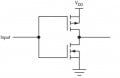
I am reading "The Art of Electronics" by Horowitz. One of the concept questions was why can't you substitute BJTs for MOSFETs in a CMOS circuit (attached). I don't know why it wouldn't work. Will someone please explain?

Thanks,
John
 

Attachments

#12

Joined Nov 30, 2010
18,224
You can do that circuit in bipolar, but the input impedances will be a lot lower because bipolar transistors need base current. Just place one resistor, like 10k, in series with the input and the circuit will switch, just like the CMOS version. Assume a 5 volt supply. When the input is 5 volts, the bottom transistor (NPN) will be on and the top transistor (PNP) will be off. When the input is decreasing below 4.4 volts, the upper transistor will conduct. The problem is that when the input voltage is 4.4v, the bottom transistor will still be conducting. That's called, "shoot through". CMOS transistors have a wider gate control voltage. If each CMOS needs 2 volts to start conducting, the overlap conducting range will be reduced to 1 volt as the input transitions from high to low or low to high. Reduce the power supply to 2 volts and the overlap range decreases to the point where a bipolar pair has a reasonable shoot through range of input voltages.

Another problem with this circuit is charge storage. Bipolar transistors take longer to shut off. The frequency limit with CMOS is about how fast you can jerk coulombs in and out of a gate that looks like a capacitor. The frequency limit with bipolar is about how fast the transistors can be cleared of junction current.

So, yes, it can be done. You just have to work with the turn-on voltages and accept the frequency limits of the parts you use.
 

DickCappels

Joined Aug 21, 2008
10,661
Consider the base-emitter junctions as diodes (because the transistors do!), then imagine the bases of the PNP and NPN connected together. What you have is two forward-biased diodes in series between Vdd and ground. In other words, nearly a short circuit, and to make matters worse (as it if could be worse) the collectors are trying to suck large currents from each other. The perfect active short circuit!


However, if you add some resistors as shown above and drive them as shown with something that is sure to make sure that one transistor or the other is off except during transitions, you can make a pretty good approximation of a CMOS inverter using bipolar transistors.
 

crutschow

Joined Mar 14, 2008
38,526
Such a circuit is normally not done with BJTs because, besides the requirement for added resistors, the static power is much higher.
As you can see from Dick's circuit, the resistors will constantly draw power even when the circuit is static.
With MOSFETs, the only current drawn in the static state is the leakage current, which is very small.
 

ScottWang

Joined Aug 23, 2012
7,501
The bjt is driving by Ib current and the mosfet is driving by Vg voltage, so they are very different, if you are not familiar with mosfet then you can using the testing circuit below to increasing the values of R1(100Ω) to decreasing the Vg voltage for N mosfet, and to see how the brightness of led changing, you can also using a VR50K or VR100K to replace R1 to try.

N type Mosfet Testing Circuit.


You can increasing the values of R2(100Ω) to increasing the Vg voltage, and to see how the brightness of led changing for P mosfet, you can also using a VR50K or VR100K to replace to R2 to try.

P type Mosfet Testing Circuit.
 
Top