 Facebook
 Google
 GitHub
 Linkedin
Hi Everyone!
About 25 or more years ago, I built a rectifier to use my AC Buzz-Box welder for DC welding. Now that I am a full on grown up, I own a DC SMAW unit & don't need this for welding.
I decided I'd like to use this at my project bench as I learn electronics. Input will be through my isolation transformer, then a variable transformer. Output will serve Project DuJour.
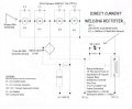
I think I wired it like I did to do this:
Before a welding arc is struck, each capacitor will allow 120hz to be the output. Once a load is impressed, the capacitors could not keep up with the demand and the diodes would take over, giving me DC at zero Hz.
The varistor & resistor were probably included to maintain a small flow so the AC would be available for the next arc strike.
But, i've forgotten more than I ever knew in the first place.
My main question pertains to frequency:
At this time, if I connect it to the transformer, my frequency meter shows 120 Hz with or without a load (resistive test loads of 800 & 1200 watts). I don't have an oscilloscope, just a simple Fluke 87.
The voltage reading on DC (122vac input) is 108 no load. I understand the drop through the diodes. With the meter on 'AC Volts', it shows 53 volts.
I wondering why I get 120hz instead of zero when it is under load. And why, with the meter set to AC, I get 53 volts instead of zero.
Is the 120hz because of the way the capacitors are wired across the diodes?
If I removed the capacitors across each diode & simply put one smoothing capacitor across DC+ & DC- do you all think this would give zero Hz?
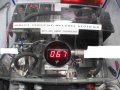
There is a drawing attached. A couple of photos are also attached. (The digital readout on the front is just the temperature inside the case, not volts.)
Thank you very much for any advice you can give. It will be appreciated & remembered. (Because now I write everything down! Hey! Where's my pencil?)
Paul
About 25 or more years ago, I built a rectifier to use my AC Buzz-Box welder for DC welding. Now that I am a full on grown up, I own a DC SMAW unit & don't need this for welding.
I decided I'd like to use this at my project bench as I learn electronics. Input will be through my isolation transformer, then a variable transformer. Output will serve Project DuJour.
I think I wired it like I did to do this:
Before a welding arc is struck, each capacitor will allow 120hz to be the output. Once a load is impressed, the capacitors could not keep up with the demand and the diodes would take over, giving me DC at zero Hz.
The varistor & resistor were probably included to maintain a small flow so the AC would be available for the next arc strike.
But, i've forgotten more than I ever knew in the first place.
My main question pertains to frequency:
At this time, if I connect it to the transformer, my frequency meter shows 120 Hz with or without a load (resistive test loads of 800 & 1200 watts). I don't have an oscilloscope, just a simple Fluke 87.
The voltage reading on DC (122vac input) is 108 no load. I understand the drop through the diodes. With the meter on 'AC Volts', it shows 53 volts.
I wondering why I get 120hz instead of zero when it is under load. And why, with the meter set to AC, I get 53 volts instead of zero.
Is the 120hz because of the way the capacitors are wired across the diodes?
If I removed the capacitors across each diode & simply put one smoothing capacitor across DC+ & DC- do you all think this would give zero Hz?
There is a drawing attached. A couple of photos are also attached. (The digital readout on the front is just the temperature inside the case, not volts.)
Thank you very much for any advice you can give. It will be appreciated & remembered. (Because now I write everything down! Hey! Where's my pencil?)
Paul
Attachments
-
 44.9 KB Views: 43
 -
 40.8 KB Views: 39
 -
 39.8 KB Views: 33


