Question about connecting a MOSFET to a motor?

Thread Starter

Patchworke

Joined Nov 6, 2020
17
You can power the gate drive off the same battery as the starter motor as shown by @crutschow . If it is like the starter motor I used, voltage drops a little due to the high motor current (>100A in my case), but the gates still turn on.

I'm really surprised; I wouldn't think the totem pole circuit would be able to handle being connected to such a high power battery. I've never worked with such high power; would my solder joints and thin-gauge wires be able to handle it? If I had to use thick-gauge wires, I don't know how I would connect them to my perforated circuit board. That's sort of the meat of my original question, though all this help with the rest of my circuit has been an extremely pleasant surprise.
Would connecting an auxiliary 12-volt alkaline battery save me the trouble of connecting high power components?
 

jpanhalt

Joined Jan 18, 2008
11,087
For the gate drive, I used ordinary PCB (1/2 oz). PCB trace amperage rating is actually a heat rating. For the very small time it is carrying current, that heating doesn't matter -- within reason. Note, the gate circuit only carries current for a small portion of time the gate is on. Don't think would use 5 mill traces, but 16 mil to 24 mil (my usual) worked fine. I am not saying 5 mil won't work, but why use such fine traces, if you don't need them?

A much bigger problem in your latest schematic is that the mosfet sources don't appear to be connected to ground or anything for that matter. ;)
 

Thread Starter

Patchworke

Joined Nov 6, 2020
17
For the gate drive, I used ordinary PCB (1/2 oz). PCB trace amperage rating is actually a heat rating. For the very small time it is carrying current, that heating doesn't matter -- within reason. Note, the gate circuit only carries current for a small portion of time the gate is on. Don't think would use 5 mill traces, but 16 mil to 24 mil (my usual) worked fine. I am not saying 5 mil won't work, but why use such fine traces, if you don't need them?
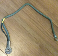
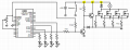
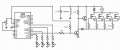
1/2 oz, 16 mil trace it is. What sort of header/terminal block/cable should I use to connect to the battery to the perforated board? I highlighted the junctions I'm concerned about below. I also included images of the 4 AWG cables with loop ends that I'm using to connect the motor to the battery. Mind you, I'm only using the 10 AWG split seen there to connect the solenoid.

1604782400488.png

A much bigger problem in your latest schematic is that the mosfet sources don't appear to be connected to ground or anything for that matter. ;)
My bad :p

1604781976557.png
 
Last edited:

jpanhalt

Joined Jan 18, 2008
11,087
1/2 oz, 16 mil trace it is. What sort of header/terminal block/cable should I use to connect to the battery to the perforated board? I highlighted the junctions I'm concerned about below. I also included images of the 4 AWG cables with loop ends that I'm using to connect the motor to the battery. Mind you, I'm only using the 10 AWG split seen there to connect the solenoid.
Perfboard? There is no way that will handle the current I think you are using. Good way to ruin a perfboard.

The units I made used welding cable. I forget whether they were 1-0 or 2-0 (probably the latter). It was a Ford tractor, long shaft 6V starter at 12V.
 

Thread Starter

Patchworke

Joined Nov 6, 2020
17
Perfboard? There is no way that will handle the current I think you are using. Good way to ruin a perfboard.
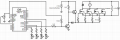
Yeah, that's what I was thinking. I think someone else mentioned it, but I don't see it. I'm thinking that using a separate battery to power the totem pole would reduce the complications of connecting those components to high power, in which case I could use a perf board or a weaker PCB. I show what that would look like (and properly grounded the source, *facepalm*) here:

1604787065766.png
 

jpanhalt

Joined Jan 18, 2008
11,087
Why did you re-implement a separate supply for the gate? Do you think a 2 Ah (max) AA "alkaline" supply will be better than a 40 Ah marine battery?
 

Thread Starter

Patchworke

Joined Nov 6, 2020
17
Why did you re-implement a separate supply for the gate? Do you think a 2 Ah (max) AA "alkaline" supply will be better than a 40 Ah marine battery?
Well, that's the question of the day, haha. If I can get away with using lower power on that branch of the circuit, it will reduce the complexity of hooking up high-power rated components. The Gates, from my understanding, turn on at 10V and 250μA, which can easily be handled by a smaller battery than my 12V 75 Ah marine battery. I don't know how to connect such small components to such big batteries. If anyone has any advice on what terminals to use and how to install them, that'd be very helpful, though!
 

jpanhalt

Joined Jan 18, 2008
11,087
Well, that's the question of the day, haha. If I can get away with using lower power on that branch of the circuit, it will reduce the complexity of hooking up high-power rated components.
Having multiple batteries, e.g., 5V for MCU, 12V for gate, 12V heavy duty for motor, would seem to me to add complexity. What happens if your gate battery goes dead?
The Gates, from my understanding, turn on at 10V and 250μA, which can easily be handled by a smaller battery than my 12V 75 Ah marine battery. I don't know how to connect such small components to such big batteries. If anyone has any advice on what terminals to use and how to install them, that'd be very helpful, though!
The gate is voltage controlled. That current figure has nothing to do with operating the gate. It is part of the definition of gate threshold voltage and represents drain to source current.
As for making connections to your heavy duty battery, remember that ALL grounds must be connected to each other, including the negative terminal of the battery to the voltage source(s) for the MCU and gates. Thus, you have at least one such connection required.
 

Thread Starter

Patchworke

Joined Nov 6, 2020
17
Having multiple batteries, e.g., 5V for MCU, 12V for gate, 12V heavy duty for motor, would seem to me to add complexity. What happens if your gate battery goes dead?
I know what you mean. I'll test it out and see how long a smaller 12V will last me. Thanks!

The gate is voltage controlled. That current figure has nothing to do with operating the gate. It is part of the definition of gate threshold voltage and represents drain to source current.
As for making connections to your heavy duty battery, remember that ALL grounds must be connected to each other, including the negative terminal of the battery to the voltage source(s) for the MCU and gates. Thus, you have at least one such connection required.
Oh, I see, I see. Thank you so much for coming to my aid, Sir, and lending me your expertise. I will be applying the things you've shared with me! I'll let you know how my project goes. If you think of anything else that's helpful, feel free to share it.
 
Last edited:

Thread Starter

Patchworke

Joined Nov 6, 2020
17
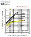
Coming back to the required 10VGS to turn on the MOSFET, I'm still confused, since the datasheet, figure 1, shows the ideal voltages included 5VGS:
1604901114420.png
 

jpanhalt

Joined Jan 18, 2008
11,087
Looking at that chart, at 5V GS and 10V DS, it passes 30A. V/I = R, so the effective resistance is 333 mΩ (0.333 Ω). Doing the same calculation at Vgs = 8V, you would predict 300A at 10V = 3.3 mΩ (0.0033 Ω). (A Vds of 10V is quite high for a mosfet that is turned fully on. This is just for illustration.)

In theory, you could try it either way, but let's look at the heating. I^2 x R = W In both cases W =297, and the device burns up. But the device is not rated for 300 A. It's maximum rating is 110 A, but even that is limited by the package to 75A. So, let's step back and see what happens when the device is passing just 30 A at each Vgs.

In the first case, 30A will still require a Vds of 10 V and the result is the same. If you cheat just a little and say just 3 V Vds, the effective resistance is 0.1Ω and heating is 90 W. That will get quite hot without a big heat sink. NB: Those voltage drops subtract from the voltage available for your motor. In the second case (Vgs= 8V), Vds is about 0.25V which equates an Rds of 0.25/30 = 8.3 mΩ and heating is just 7.5W.

Everyone here has told you that the IRF3205 requires more than 5 V to turn on completely. Yes, it will pass current with a Vgs of only 5V, but the voltage drop across the device will be much higher than with the recommended 10V to 12V Vgs. That higher effective resistance will cause a decrease in available to your motor and a lot of heat in the mosfets.

If you still have doubts and want to use 5V, maybe it is time for you to get your fingers wet burned and do the experiment?
 

jpanhalt

Joined Jan 18, 2008
11,087
It's not personal, I'm just hearing conflicting things from other sources, so I'm trying to work through it.
I do hear that any VGS above 10V will result in too low of RDS, 10V is the ideal. Do you agree that 10V is better than 12V?
Look at the graph.

I guess I need to refer you to those "other" sources in the future.

Good luck.
 

crutschow

Joined Mar 14, 2008
38,622
I'm just hearing conflicting things from other sources, so I'm trying to work through it.
I do hear that any VGS above 10V will result in too low of RDS, 10V is the ideal. Do you agree that 10V is better than 12V?
Your "other sources", whoever they are, are full of excrement from the rear of a bull.
There's no such thing as "too low of RDS" for a MOSFET used as a switch.
You want Rds to be as low as possible to minimize heating when it is on.

Those curves you show with varying values of Vgs are only if you want to use the MOSFET as a linear amp, not as a switch.
Vgs of 10V is the minimum for that transistor to fully turn it on as a switch. That's why that value is shown in the data sheet when they test the Rds value.
Anything above that Vgs value will not have much effect (as long as you stay below the Vgs(max) rating which can zap the gate oxide).
 
Top