Question about capacitors

Thread Starter

Singh_Wireliner

Joined Apr 9, 2025
8
Hello,

I am new to this forum. I am a drilling engineer with considerable experience in oil and gas with exposure to both onshore and offshore operations across the world. However, my knowledge of electronics is extremely limited. I have been studying electronics as a hobby (there is something magical about it... drilling is really prosaic, believe me!). It does feel like I am wasting my time but i guess its no worse than fishing or skiing and it gives me joy.

I was going through some courses online but it does seem they are a bit superficial? Any suggestions?

Also, would it be possible to raise questions / discuss here? Really elementary / stupid questions from me? For example, I still cant understand why a capacitor passes high frequency AC but not low frequency AC? Should not make a difference, should it?

Thanks in advance...

Regards,
Singh
 

BobTPH

Joined Jun 5, 2013
11,502
still cant understand why a capacitor passes high frequency AC but not low frequency AC? Should not make a difference, should it?
Perhaps the reason you cannot understand it is because it is not true.

If you had a voltmeter with infinite impedance (i.e. draws no current) and you connect it through a capacitor to an AC source, it will correctly read the AC voltage at any frequency.

Why? Because with no current flowing, the voltage across the capacitor never changes. For simplicity, assume that voltage is zero. So in your series circuit, you have the AC source minus the voltage across the voltage across the capacitor (0) and the output to the voltmeter is just the AC voltage.

Now give the voltmeter some resistance. Now when you measure the voltage the capacitor will charge and discharge through the resistor during each cycle. Any voltage across the capacitor is subtracted form the AC source, so it reads lower than it should.

The lower the frequency, the more the capacitor will charge. So at low frequencies, the capacitor voltage will get higher in each cycle, subtracting more from the AC voltage seen by the meter. Whereas, at high frequencies the capacitor has little time to charge, so less voltage is lost.

A capacitor alone does not drop a voltage dependent on frequency, it is the combination of a capacitor and resistor that does so. And that combo is called a high pass filter.
 
Last edited:

Tonyr1084

Joined Sep 24, 2015
9,744
Singh_Wireliner Welcome to AAC. Yes, you can ask any questions you like. No such thing as stupid questions. Just sometimes answers.

Capacitors are somewhat mysterious beasts to me too. I've come to think about caps this way: They do not conduct. They do not conduct because there is no physical connection inside them. They charge and discharge. So DC will not pass through them. AC will. Actually, that's not even true. Since there is no connection internally there is no conduction other than the charging and discharging going on.

Think of a cap as you standing between two walls. You have a spring. Big or small - it's a spring. You take that spring and press it against one wall. Now there's pressure on one wall. You've done all the work you can do - you've pushed with all your might to compress that spring against that wall. But the other wall has no pressure. What you've done is the equivalent of DC. Instead, you now take that spring and push it against the opposite wall. The cap has now been charged in the other direction. But again, you've reached your max. No further work is being done. But with AC you are pushing the spring against one wall, then the other, then the first, then the other. Over and over. You are doing work. And it seems like AC is passing through the capacitor.

Take a large capacitor and a small battery and lamp. Connect the lamp, battery and cap in series. The lamp will light up. But it will dim until it goes out. That's the action of current flowing into the capacitor, just like you pressing the spring against one wall. Now reverse the polarity. Now the lamp will light again with greater intensity. It will light with the voltage of the battery PLUS the stored voltage from the cap. But just as in the first instance the light will dim until it goes out. Now you've pushed the spring against the other wall. Again, you've done all you can and no further current is flowing.

BUT AC is different. It is reversing the polarity constantly. So the cap charges in one direction then discharges into the opposite direction, then charges in that opposite direction again. And again. And again. During the time you spent in-between two walls you pressed that spring against one wall or the other. If all you did was press it against one wall you've done all the work you can. But if you alternate from side to side you continue to do work. AC in a cap is doing the same thing. It seems like it's conducting AC Voltage. It's not. It's conducting the CURRENT. Of course that current depends on other factors like voltage and resistance. Think of it as a vibrator. It shakes from one side to the other. If it only went to one side it wouldn't vibrate.

In DC applications a cap can act like a reservoir or battery. Charging and discharging to maintain a steady output (relatively speaking). In AC applications it can act like a filter, blocking slow changes (or frequencies) while passing more easily high frequencies. Caps are used in crossover networks blocking base waves from reaching tweeters, which can destroy the tweeters. But caps alone are not the be-all - end-all of crossover networks. That's another subject.
 

nsaspook

Joined Aug 27, 2009
16,297
Greatly simplified. Electrical engineering capacitors (vs the physics example capacitors) are sort of special wires, that's why they are often treated (a circuit theory model that works under most common conditions but does not explain how it works) as a black-box that can pass current.

The EM fields, surrounding the wire (a good conductor), that actually carry the electrical energy in a circuit (not the electrons) are in free space external to the wires surface. Those external but very close to the wire EM fields can bridge a small gap (the dielectric) from one wire to the next wire if they overlap but don't touch by some amount in space. We call this ability to transfer electric field energy across space, Capacitance.

This gap (an insulator of vacuum, air or a dielectric material that can rearrange charges, but not flow charges in response to a electric field) stores and releases electrical energy in response to external fields that cause charge separation (the slight movement or rearrangement of free charges in the wire conductors) on the two wires that are very close but not touching.
 
Last edited:

ElectricSpidey

Joined Dec 2, 2017
3,326
Tony try to remember electricity has 2 forces at play in most cases...attraction and repulsion, so your spring analogy is only half correct.

In other words, while you are compressing one spring you are also expanding another.
 

nsaspook

Joined Aug 27, 2009
16,297
http://amasci.com/emotor/cap1.html

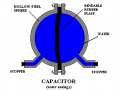
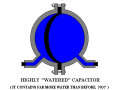
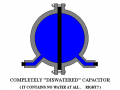
If we need to use an analogy, this is a much better one.
Now think: in this analogy, water corresponds to electric charge. How much water have I put into my iron sphere? None! The sphere started out full, and for every bit of water that I took out of one side, I put an equal amount into the other at the same time. Same as when running a current through a conductor. When the pump pushed water into one side, this extra water also forced some water out of the other side. No water passed through the rubber, instead there was some rubber-current in the divide. Even so, essentially I drove a water current through my hydraulic capacitor, and this current pushed on the rubber plate and bent it sideways. Where is the energy stored? Not in the water, but in the potential energy of the stretched rubber plate. The rubber plate is an analogy to the electrostatic field in the dielectric of a real capacitor.


1744209171835.png
1744209196061.png

1744209220386.png
 

MrChips

Joined Oct 2, 2009
34,745
There are three fundamental circuit elements that you need to master, resistor, inductor, and capacitor.
All three can be simplified using the word reactance, but you need the math to explain and differentiate their behaviors and functions.

Just think of a capacitor as two parallel plates. It is an open circuit. DC current cannot pass across the capacitor.
The two plates can hold charge. Hence a capacitor can be used as a reservoir of charge and to prevent DC voltages from changing too rapidly.

Since the charge (and voltage) across the plates hold steady, if you change the voltage on one side of the capacitor, the other side has to change too, as long as it is not heavily tied down through a heavy load (low value resistor). Hence changing voltage (AC) can be transferred across the capacitor while DC cannot. This effect is dependent on rate of change. Fast changing voltages get transferred more easily than slow changes, and not at all for DC.

Note: We no longer restrict the usage of DC and AC to mean direct current and alternating current. We use it to refer to voltages as well. Furthermore, we use DC to mean zero frequency voltages and AC to mean non-zero frequency voltages.
 

nsaspook

Joined Aug 27, 2009
16,297
You can think of it that way using the black-box model but the physics reality is that capacitors don't store charge. The two plates have charge and the amount of change never changes. They hold electrical energy by charge separation across space.


ElectricSpidey

Joined Dec 2, 2017
3,326
From the above link: (in post #9)

" When we "charge" a conventional metal-plate capacitor, the power supply pushes electrons into one plate, and the fields from these extra electrons reach across the gap between the plates, forcing an equal number of electrons to simultaneously flow out of the other plate and into the power supply. "

This is the major flaw of most water and gravity analogies, as it only represents one of the two forces at work on the electrons, at the very least the analogy should use 2 pumps...one pushing the electrons and one pulling them,
 

nsaspook

Joined Aug 27, 2009
16,297
From the above link: (in post #9)

" When we "charge" a conventional metal-plate capacitor, the power supply pushes electrons into one plate, and the fields from these extra electrons reach across the gap between the plates, forcing an equal number of electrons to simultaneously flow out of the other plate and into the power supply. "

This is the major flaw of most water and gravity analogies, as it only represents one of the two forces at work on the electrons, at the very least the analogy should use 2 pumps...one pushing the electrons and one pulling them,
"Charge" is being used in a facetious manner in those comments from the link. I agree about analogies but they can be helpful.
 

Futurist

Joined Apr 8, 2025
739
Hello,

I am new to this forum. I am a drilling engineer with considerable experience in oil and gas with exposure to both onshore and offshore operations across the world. However, my knowledge of electronics is extremely limited. I have been studying electronics as a hobby (there is something magical about it... drilling is really prosaic, believe me!). It does feel like I am wasting my time but i guess its no worse than fishing or skiing and it gives me joy.

I was going through some courses online but it does seem they are a bit superficial? Any suggestions?

Also, would it be possible to raise questions / discuss here? Really elementary / stupid questions from me? For example, I still cant understand why a capacitor passes high frequency AC but not low frequency AC? Should not make a difference, should it?

Thanks in advance...

Regards,
Singh
Good books are hard to find, you could buy ten book on introductory electronics and find most of them are just hard to learn from.

So I will recommend one that I rate highly.

1744222042627.png

Despite the title and "inventors" this is a seriously pragmatic book, I think the title is in fact good but initially it put me off.

If you were truly inventing stuff that included electronics then you will benefit from this book unless you already have a degree in the subject.

It really covers a lot of stuff, not just theory but some history, lots of practical stuff too like tolerance, power, heat, noise for someone coming in as newcomer and hobbyist this is a great book.
 

Thread Starter

Singh_Wireliner

Joined Apr 9, 2025
8
Perhaps the reason you cannot understand it is because it is not true.

If you had a voltmeter with infinite impedance (i.e. draws no current) and you connect it through a capacitor to an AC source, it will correctly read the AC voltage at any frequency.

Why? Because with no current flowing, the voltage across the capacitor never changes. For simplicity, assume that voltage is zero. So in your series circuit, you have the AC source minus the voltage across the voltage across the capacitor (0) and the output to the voltmeter is just the AC voltage.

Now give the voltmeter some resistance. Now when you measure the voltage the capacitor will charge and discharge through the resistor during each cycle. Any voltage across the capacitor is subtracted form the AC source, so it reads lower than it should.

The lower the frequency, the more the capacitor will charge. So at low frequencies, the capacitor voltage will get higher in each cycle, subtracting more from the AC voltage seen by the meter. Whereas, at high frequencies the capacitor has little time to charge, so less voltage is lost.

A capacitor alone does not drop a voltage dependent on frequency, it is the combination of a capacitor and resistor that does so. And that combo is called a high pass filter.
 

Thread Starter

Singh_Wireliner

Joined Apr 9, 2025
8
Perhaps the reason you cannot understand it is because it is not true.

If you had a voltmeter with infinite impedance (i.e. draws no current) and you connect it through a capacitor to an AC source, it will correctly read the AC voltage at any frequency.

Why? Because with no current flowing, the voltage across the capacitor never changes. For simplicity, assume that voltage is zero. So in your series circuit, you have the AC source minus the voltage across the voltage across the capacitor (0) and the output to the voltmeter is just the AC voltage.

Now give the voltmeter some resistance. Now when you measure the voltage the capacitor will charge and discharge through the resistor during each cycle. Any voltage across the capacitor is subtracted form the AC source, so it reads lower than it should.

The lower the frequency, the more the capacitor will charge. So at low frequencies, the capacitor voltage will get higher in each cycle, subtracting more from the AC voltage seen by the meter. Whereas, at high frequencies the capacitor has little time to charge, so less voltage is lost.

A capacitor alone does not drop a voltage dependent on frequency, it is the combination of a capacitor and resistor that does so. And that combo is called a high pass filter.
Thanks for the answer. I am not sure i got it but will read through it again. But just to be sure the impedance of a capacitor is the ratio of voltage to current (same as a resistor). Now the impedance offered by a capacitor to high frequency is lower than for low frequency. This means that for high frequency AC current, the current for the same voltage will be higher. But why should that be so? if the higher frequency means that the plates of the capacitor get less time to charge then less electrons should flow which should mean lower current... nei?
 

MrChips

Joined Oct 2, 2009
34,745
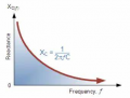
Now you are asking for the reactance of a capacitor.

The formula for reactance of a capacitor is:
Xc = 1 / (2πfC)

where,
Xc = reactance in ohms
f = frequency in hertz
C = capacitance in farads

Thus, the reactance decreases with increasing frequency.

1744231441380.png
 

Thread Starter

Singh_Wireliner

Joined Apr 9, 2025
8
There are three fundamental circuit elements that you need to master, resistor, inductor, and capacitor.
All three can be simplified using the word reactance, but you need the math to explain and differentiate their behaviors and functions.

Just think of a capacitor as two parallel plates. It is an open circuit. DC current cannot pass across the capacitor.
The two plates can hold charge. Hence a capacitor can be used as a reservoir of charge and to prevent DC voltages from changing too rapidly.

Since the charge (and voltage) across the plates hold steady, if you change the voltage on one side of the capacitor, the other side has to change too, as long as it is not heavily tied down through a heavy load (low value resistor). Hence changing voltage (AC) can be transferred across the capacitor while DC cannot. This effect is dependent on rate of change. Fast changing voltages get transferred more easily than slow changes, and not at all for DC.

Note: We no longer restrict the usage of DC and AC to mean direct current and alternating current. We use it to refer to voltages as well. Furthermore, we use DC to mean zero frequency voltages and AC to mean non-zero frequency voltages.
Fast changing voltages get transferred more easily than slow changes - why?
 

Thread Starter

Singh_Wireliner

Joined Apr 9, 2025
8
From the above link: (in post #9)

" When we "charge" a conventional metal-plate capacitor, the power supply pushes electrons into one plate, and the fields from these extra electrons reach across the gap between the plates, forcing an equal number of electrons to simultaneously flow out of the other plate and into the power supply. "

This is the major flaw of most water and gravity analogies, as it only represents one of the two forces at work on the electrons, at the very least the analogy should use 2 pumps...one pushing the electrons and one pulling them,
maybe stupid question but if you have a capacitor where instead of the dielectric material you have something between the plates which is totally impervious to electrical fields... would the plates still charge? the plate connected to the negative end of the battery would get full of electrons...and the other plate would lose electrons as they would drain into the positive side of the battery..no?
 
Top