 Facebook
 Google
 GitHub
 Linkedin
I have a wine cooler that the circuit board keeps blowing it's fuse. I tested some of the components most of the diodes and found and replaced one bad diode but I don't really know how to test everything else or where I should start for the problem I'm having.
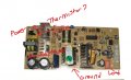
I've attached an image of what I know. Is that one component a thermistor? how do I test it? from what I understand about thermistors this could very well be my issue but I don't know what a working one should test like. the numbers on it are "005 04". I replaced the one diode that tested at 0.002 both directions. it was a 1n4007 but all I had laying around was a 1n4001 (figured it would be enough to confirm the issue then I could replace it with a 7 later on) put it in and tested at 0.56 but didn't fix my issue, I replaced and blew another fuse.
the amperage coming out of my power supply is ~12a (if i'm testing correctly) at ~118v. The fuse is rated at 250v 2.5a (same rating as the original fuse) and it's fast acting) but when i test across the fuse leads I'm getting the same ~12a that is coming from the power supply (again if i'm testing correctly) but I assume that should be dropped across the fuse some where at 2.5 or lower? or does a board like this require a slow blow? it looked like fast to me and there was no indication on it otherwise.
I'm still pretty green with circuits. been a while since I took any sort of engineering but I do have a pretty good grasp on how "most" of the components should work just not how to confirm they are working the way the should.
Attachments
-
 72.8 KB Views: 19


