 Facebook
 Google
 GitHub
 Linkedin
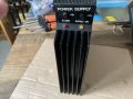
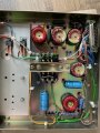
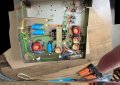
Please could anyone give me information about this, especially the pinout (25)pin, and schematic if possible was told this was a microwave radio psu thanks in advance.. should read PYE/ phillips
Attachments
-
 2.5 MB Views: 16
 -
 2.1 MB Views: 16
 -
 1.1 MB Views: 16


