PWM of Buck Converter

Thread Starter

Peter523

Joined Aug 15, 2021
97
Hello,

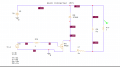
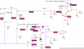
I constructed the buck converter shown below. As i saw, in most buck converter schematics the pulse generator is connected like i did (positive side on the transistor gate and negative on the drain). My problem is that when i measure the gate voltage is a pulse of approximately 10Volts isntead of the 5Volts i gave to V2 (of the pulse generator) Furthermore, if i would like to construct it to a pcb and connect a pwm (pulse width modulation) signal from a microcontroller (instead of pulse generator of PSpice) how will this connection be done?

Thank you.
Screenshot_1.png
 

Ian0

Joined Aug 7, 2020
13,230
Three possibilities:
1) Use a half-bridge driver such as FAN7382
https://www.onsemi.com/pdf/datasheet/fan7382-d.pdf
(and ignore the LIN and LO connections)

2) Does one side of your load have to be connected to ground? Could the load be connected between the output and V+ instead?

3) Could the V+ connection of the microcontroller be connected to the V+ of this circuit (meaning that the 0V connection to the microcontroller is NOT connected to the 0V for this circuit)? If so, you would need a P-channel MOSFET.
 

Thread Starter

Peter523

Joined Aug 15, 2021
97
Three possibilities:
1) Use a half-bridge driver such as FAN7382
https://www.onsemi.com/pdf/datasheet/fan7382-d.pdf
(and ignore the LIN and LO connections)

2) Does one side of your load have to be connected to ground? Could the load be connected between the output and V+ instead?

3) Could the V+ connection of the microcontroller be connected to the V+ of this circuit (meaning that the 0V connection to the microcontroller is NOT connected to the 0V for this circuit)? If so, you would need a P-channel MOSFET.
1)The FAN7382 will be connected between mcu pwm signal and transistor gate?

2)Could you explain what do you mean with V+ ? I connected load in the standard way which i saw in many buck converter designs

3)Again what do you mean with V+?
 

ericgibbs

Joined Jan 29, 2010
21,541
hi Peter,
This is a problem that happens when you do not assign a label to points of measurement of a
circuit.
Put some ID labels at the Nodes..:)
E

eg: +Vin, +Vout, Vgate etc ......
 

BobTPH

Joined Jun 5, 2013
11,619
The cicuit you hsve might work as long as the micro and its power supply are isolated from your high voltage supply, i.e. no common ground.

You would connect the ground of the micro to the source of the MOSFET and the output of the micro to to gate.

However, thus puts the entire micro circuit at about 200V above ground, making it a shock hazard which would have to be enclosed and insulated from touch.

I do suspect that the circuit would have a problem switching at that frequency (400 KHz) when driven by micro output.

The better alternative is to use a high side gate driver, as @Ian0 suggested, which would allow the micro to share a common ground as well as provide the high current to the gate allowing it to switch faster.

Bob
 

Thread Starter

Peter523

Joined Aug 15, 2021
97
The cicuit you hsve might work as long as the micro and its power supply are isolated from your high voltage supply, i.e. no common ground.

You would connect the ground of the micro to the source of the MOSFET and the output of the micro to to gate.

However, thus puts the entire micro circuit at about 200V above ground, making it a shock hazard which would have to be enclosed and insulated from touch.

I do suspect that the circuit would have a problem switching at that frequency (400 KHz) when driven by micro output.

The better alternative is to use a high side gate driver, as @Ian0 suggested, which would allow the micro to share a common ground as well as provide the high current to the gate allowing it to switch faster.

Bob
Ok. So the gate driver is an IC that will be connected from one side to microcontroller's pwm output and from the other side to mosfets gate making it switch? How can i find this gate driver that suits my mosfet? Is FAN7382 that @Ian0 suggested suitable?
 

Ian0

Joined Aug 7, 2020
13,230
These are the three choices.
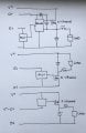
4FDDB5F2-73BE-4908-BABE-970875706202.jpegThe FAN7382 is suitable. (Would I be so mean as to suggest something that wouldn’t work?) There are plenty of other choices, just look up “half bridge driver”. If the application circuit looks like the drawing above, you probably have the right type of device. Some of them have the diode built in.
One thing this circuit can’t do is high duty cycles, or keep the MOSFET switched on indefinitely. If you need 100% duty cycle use one of the other two circuits.
 

Thread Starter

Peter523

Joined Aug 15, 2021
97
These are the three choices.
View attachment 245725The FAN7382 is suitable. (Would I be so mean as to suggest something that wouldn’t work?) There are plenty of other choices, just look up “half bridge driver”. If the application circuit looks like the drawing above, you probably have the right type of device. Some of them have the diode built in.
One thing this circuit can’t do is high duty cycles, or keep the MOSFET switched on indefinitely. If you need 100% duty cycle use one of the other two circuits.
I think that the first choice i closer to the circuit i have (first posted). As you say, FAN7382 needs 12V voltage supply. Is there any gate driver that may operate with a lower supply, e.g 5Volts?
 

Ian0

Joined Aug 7, 2020
13,230
I think that the first choice i closer to the circuit i have (first posted). As you say, FAN7382 needs 12V voltage supply. Is there any gate driver that may operate with a lower supply, e.g 5Volts?
Not that I know of.
It produces the gate drive voltage from its supply voltage using a charge-pump, and 5V-less-a-diode really isn't enough for most MOSFETs. It would be limted to logic-level MOSFETs
As it works up to 500V, it is intended to drive 500V MOSFETs, and logic-level MOSFETs are pretty scarce at that voltage!
 

BobTPH

Joined Jun 5, 2013
11,619
@Ian0:

What is wrong with my option of an isolated supply for the micro, N-channel, with ground of micro connected to source?

Not suggesting that is the best solution, only that it would work. I would go for the high side driver, for the reason I gave in my previous post.

Bob
 

Thread Starter

Peter523

Joined Aug 15, 2021
97
@Ian0:

What is wrong with my option of an isolated supply for the micro, N-channel, with ground of micro connected to source?

Not suggesting that is the best solution, only that it would work. I would go for the high side driver, for the reason I gave in my previous post.

Bob
Could you explain me your suggestion?
 

Thread Starter

Peter523

Joined Aug 15, 2021
97
Not that I know of.
It produces the gate drive voltage from its supply voltage using a charge-pump, and 5V-less-a-diode really isn't enough for most MOSFETs. It would be limted to logic-level MOSFETs
As it works up to 500V, it is intended to drive 500V MOSFETs, and logic-level MOSFETs are pretty scarce at that voltage!
With a quick search i found UCC27322 that could be a solution. Do you think it may be suitable?
 

Thread Starter

Peter523

Joined Aug 15, 2021
97
Yes that’s the one. If you have a big MOSFET the MCU pin won’t have enough output current to charge its gate capacitance quickly, and the UCC27322 will give it some extra drive.
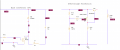
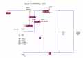
Ok thank you very much, the circuit seems to operate correctly. Now i want to add the overvoltage protection depicted below but when i add it before the load (as depicted) the circuit doesn't operate at all. Is there another way that it should be connected?
 

Attachments

Ian0

Joined Aug 7, 2020
13,230
Ok thank you very much, the circuit seems to operate correctly. Now i want to add the overvoltage protection depicted below but when i add it before the load (as depicted) the circuit doesn't operate at all. Is there another way that it should be connected?
As the load is no longer connected to 0V, delete that 0V connection from the load! Then it should work.
 

Thread Starter

Peter523

Joined Aug 15, 2021
97
As the load is no longer connected to 0V, delete that 0V connection from the load! Then it should work.
Hello again,

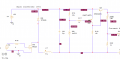
except for overvoltage protection i would also like to add current and voltage measurement circuits on the load as depicted (the whole circuit) but after the change on the circuit they dont seem to operate properly.Screenshot_1.pngScreenshot_2.png
 
Top