I never really liked PWM signals being called digital.
Most pwm circuits operate in continuous time and there are no discrete pulse widths generated, they can be continously variable.
I haven't mentioned it yet but I think you deserve high praise for taking the time to compile this treatise on PWM. Next to LEDs and Microcontrollers, I think PWM is a frequent topic of post here in the forum.
In the post linked to above, you show a comparator with a potentiometer and several representative outputs. The two lower output plots are indicative of different settings of the potentimeter. I wonder if it would be a good idea to note on each, the setting of the potentiometer that yielded the output.
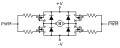
Do you suppose anyone is going to quibble over the fact that the two high-side MOSFET devices in your H-bridge (in the motor driver illustration) requires a high-side driver to switch properly?
I think it would be helpful if the diagram showing the sinusoid to PWM waveform would benefit from being enlarged. This would provide greater resolution of the resulting PWM signal. I think it would make the concept clearer to those encountering PWM for the first time.
If you create a path through the MOSFETs that drives a motor in one direction using a PWM signal, you do not want the reverse direction to be activated during the resting portion of the PWM.
From a grammatical persective, I think that the last sentence in the following paragraph.
Efficiency in this case is measured as wattage. If you have a SMPS with 90% efficiency, and it converts 12VDC to 5VDC at 10 Amps, the 12V side will be pulling approximately 4.6 Amps. The 10% (5 watts) not accounted for will show up as waste heat. While being slightly noisier, this type of regulator run much cooler than their linear counterparts.
Efficiency in this case is measured as wattage. If you have a SMPS with 90% efficiency, and it converts 12VDC to 5VDC at 10 Amps, the 12V side will be pulling approximately 4.6 Amps. The 10% (5 watts) not accounted for will show up as waste heat. While being slightly noisier, this type of regulator runs much cooler than its linear counterparts.
If you create a path through the MOSFETs that drives a motor in one direction using a PWM signal, you do not want the reverse direction to be activated during the resting portion of the PWM.
It is a bidirectional controller. If you have a 50% PWM signal, the motor will turn in neither direction, two directions being balanced. 0% is full rotation in one direction, and 100% is full rotation in the other direction. Motors, being basically inductive, will reject the high frequency components and respond to the low frequency component, much like speakers. It is simplified, but the base concept is valid.
You can drive a motor one way with one transistor, but for full control in both directions you need a H-Bridge.
I haven't mentioned it yet but I think you deserve high praise for taking the time to compile this treatise on PWM. Next to LEDs and Microcontrollers, I think PWM is a frequent topic of post here in the forum.
In the post linked to above, you show a comparator with a potentiometer and several representative outputs. The two lower output plots are indicative of different settings of the potentimeter. I wonder if it would be a good idea to note on each, the setting of the potentiometer that yielded the output.
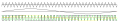
Actually the point I'm trying to make is the symmetry of the triangle wave doesn't matter. I lifted this image from a thread that is currently dormant.
I may have missed my mark a bit. They were originally separate, but I merged them trying to lay the flow of the article a bit smoother.
Do you suppose anyone is going to quibble over the fact that the two high-side MOSFET devices in your H-bridge (in the motor driver illustration) requires a high-side driver to switch properly?
Probably. If you have a better thought how to draw it, sketch it up as ugly as you like and I'll pretty it up. My thought is a 12 V power supply would do the job, top gets 0V, bottom gets 12V. Other side gets opposite.
I think it would be helpful if the diagram showing the sinusoid to PWM waveform would benefit from being enlarged. This would provide greater resolution of the resulting PWM signal. I think it would make the concept clearer to those encountering PWM for the first time.
I'm going to add captions to the pictures. If people like the wording (in other words, don't actively mention it) I'll merge it with the pictures before I pack the article.
I still have the second illustration to redraw, but I'm almost finished here.
Might mention that PWM has been commonly used in high power AM and Shortwave broadcasting since the early 1980s. It's functionality is not limited to solid state devices, the Harris MW-50, for example, is all vacuum tube ("hollow state") except for the low power PWM exciter.
 Facebook
 Google
 GitHub
 Linkedin