I think “efficiency” is the fewest components, simplest implementation and/ or most understandable to a noob from the TS’s point of view, while most of us automatically think of energy efficiency & matters life maximization.
Taking care of my FIL with ALZ taught me the value of letting things go that used to seem important. Turns out they weren't as important as I thought they were.
I think “efficiency” is the fewest components, simplest implementation and/ or most understandable to a noob from the TS’s point of view, while most of us automatically think of energy efficiency & matters life maximization.
So you are not really worried about efficiency, just the dissipation in the transistor.
That's different from increasing the overall efficiency by using PWM, which your circuit won't do.
I hadn't actually realized it, but I think you're right. I'm mostly concerned about minimizing dissipation in the transistor. Although, even though I were to use a DC - DC converter, I'd still have transformer losses because I'd still have to step the mains voltage down through one before the converter can further bring it lower to charge the battery, right? I can't think of even trying a 325VDC to 12VDC DC - DC convertor.
Well, I can't think of a reason it wouldn't. I'll try later when I find the time. The "PWM5 solar charge controller" by a guy on youTube called Jullian Illet works on almost the same principle. His is a 2 stage charger. In the bulk charge, the full output of the panel(s) is used, however, in the float charge, he uses PWM. In essence, the panels' output current is limited from raising the voltage above 13.5v.
Do you also think it would work to charge it at 1200A for 1ms out of each second? Like your scheme, that also gives you an average charging current of 1.2A.
Ignoring the exaggeration, I think it would. That's why I want to try it. A 1 second period is far too long and I think the 1200A thing is obvious so I won't get into that!
Although, even though I were to use a DC - DC converter, I'd still have transformer losses because I'd still have to step the mains voltage down through one before the converter can further bring it lower to charge the battery, right?
Thanks Bordodynov. I was trying to avoid switching circuits but this looks tempting judging by it's simplicity.
A few questions, 1) What voltage is Vin?
I may have been a bit misleading in the thread title, I guess what I meant to ask was a current limiter. This brings me to the second question, If V2 is darwing less than 2 amps, how would the circuit behave?
The primary reason I'm biased against DC-DC converters is I have no way is monitoring the circuit in the prototype phase coz I haven't got a scope yet. So there would be no way of troubleshooting a problem or even checking for instabilities if any, but if it comes to it, I might have no choice but to build one blindly.
Since you are not controlling the switching frequency, why do you think it will be low?
As you stated, the current ramp-up will be determined by the load (mainly the circuit stray inductance of perhaps a few microhenries) and, since that is low, the ramp-up will be fast and the PMW frequency thus also high.
Alright, I apologies if I mixed things up, but there were 2 ideas originally.
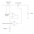
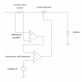
The first (shown above) was to use a comparator with hysteresis to compare the charge current (converted to voltage by a shunt resistor via a differential amp) against a reference voltage. If the output current is below the threshold, the comparator would turn the output transistor on until the threshold is reached (2.2 amps for example) and then turn off. I'd have an RC filter on the output of the differential amp so that it's output ramps down rather than turn off instantly (as does the actual current). During the ramp (down) the low threshold of the comparator would eventually be reached (corresponding to about 1.8 amps) and the output transistor would be turned back on. In this case, the ON - OFF frequency would be determined by the input resistance of the load. If the current rises fast when the transistor is turned on, the frequency would be fast and vice versa.
The second is a lot simpler and it's the one I have more faith will work.
The comparator would be replaced by an Arduino.
The shunt voltage from the differential amp will feed into an analog input on the Arduino. A PWM pin will run the output transistor. In this version, the Arduino will determine what to do depending on what readings it receives from the differential amp. When turned on, the Arduino would read the current and if it's higher than desired, it will keep lowering the PWM until the target is reached. If the current is low, the PWM goes up correspondingly. In this version, the frequency is fixed because it runs from the MCU PWM pin.
I'll be going with the Arduino version, sorry about the mix up.
Yes, it's annoying when a TS asks for advice and then argues that he's right and the advice from several posters is wrong.
Why ask for advice if you accept only advice that agrees with your preconceived ideas?
Sorry it appears that way, we were probably discussing different circuits all the while, my fault. I'll be going with an MCU and controlling the transistor with a PWM pin. Frequency would be fixed (at about 512 hz or there about) and the duty cycle would vary from 0 - 255 (0 - maximum current the transformer can supply).

 Facebook
 Google
 GitHub
 Linkedin