Push Pull Frequency question

Thread Starter

Buddy_Jones

Joined Feb 25, 2018
8
Hi
This is my first post. I am just hobbyist but I don't know where to turn except to someone who might have a clue.
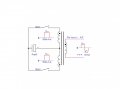
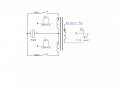
I built a push pull converter, still working through some things on it, but I am stumped and can't find an answer.
I am trying to run 25 khz as calculated for the transformer. Since I have 2 switches my guess was each switch would run at 50 khz 48% duty cycle the output would equal 25 khz. The scope says I am wrong. My thought was it end up like AC where 1 hertz is a completed sine, both the positive and negative get counted as 1. Maybe its different with square wave, maybe I'm clueless with my scope. Either way any insight on that would be great.

Thanks in advance.
 

ebp

Joined Feb 8, 2018
2,332
You should be able to find all sorts of useful info at TI. TI acquired Unitrode a few years ago, then National Semi. All three had switcher products. Unitrode published tons of stuff that covers fundamentals.

That circuit is very perilous. There is nothing to limit current in the switches. An imbalance in ON times between the two can rapidly cause "staircase" saturation of the transformer core, at which point one of the windings becomes a short piece of wire with no inductance and something goes bang. Putting capacitors across the switches means each switch must discharge its capacitor each cycle. You have no filter inductor in the secondary which means that when a switch first turns on the current is essentially unlimited except by component resistances.

Did you make the transformer or buy it off the shelf?
 

AnalogKid

Joined Aug 1, 2013
10,987
There is too much secret information missing:

What are PS1 and PS2?

What are MD1 and MD2?

Where do the signals for PL5 and PL6 come from?

Please post a scope image of the two driving signals so we can see the timing relationships. After all, that is what you are asking about.

Please post a schematic of the transformer showing the windings and taps.

ak
 

Thread Starter

Buddy_Jones

Joined Feb 25, 2018
8
Yes I wound the transformer myself. I am very aware of all the pitfalls. Again this is just a hobby project and I am not trying to perfect it here. I enjoy putting things together and learning why all the parts are needed in a given setup. I slowly piece them together to watch each component and its reaction overall.
I thought I had simple question that would pertain to any push pull circuit. So let me rephrase it and maybe I can get rid of all the concerns about what I am building at my pleasure for nothing but a learning hobby.

I have not been able to find an answer to this in any book or on any website. Sorry..

In the ideal push pull Isolated converter circuit. Free from any flaw with perfect timing and perfect craftsmanship how do you figure the frequency. I have both side running 50 khz at 48% duty cycle. Would the output of the transformer be 50 khz or 25 khz. Like I said is it like AC or is there another way of looking at it.

I am grateful for the pointers and the interest but I am just trying to figure this frequency thing out. All I need is how to figure it.

Thanks
 

AnalogKid

Joined Aug 1, 2013
10,987
It isn't. And, I don't know what your mean by "different than AC". If you put 50 kHz into one side of a transformer, you are going to get 50 kHz out of the other side.

ak
 

AnalogKid

Joined Aug 1, 2013
10,987
Rather than react to an answer you don't like, concentrate on the quality of the question. The fact that you are driving the transformer with two different waveforms doesn't matter because both waveforms are the same frequency. That is just how transformers work. If the transformer were part of an analog mixer circuit, the output would be either 100 kHz or 0 Hz, the sum and difference frequencies.

Which raises a question - why do you think a hunk of iron can divide a frequency in half?

The reason I asked for a schematic of the transformer windings is because the order and direction of the windings are critical to how the transformer responds to the energy moving through it. If the transformer is would correctly, and the two driving waveforms are 180 degrees out of phase, then you are driving only 1/2 of the transformer with each transistor ON period, moving current through the primary first to the left and then to the right (based on the orientation of the transformer in your drawing. But each waveform is controlling the primary only 1/2 of the time, so my real question to you is not why you think the resultant energy wave should be 25 kHz, but why you don't think it should be 100 kHz.

ak
 

ebp

Joined Feb 8, 2018
2,332
If you don't already have something like it, I recommend getting LTSpice from Linear Technology. It is free and the learning curve for simple stuff is pretty gentle. It would allow you to simulate a version of your circuit using mostly "ideal" components, like a transformer that won't saturate and doesn't have any leakage inductance that makes waveforms look weird until you fully understand what is expected. You can put voltage and current "probes" all over the place so you can see magnitude and timing relationships - things that can be hard to do in a real switcher without special and expensive instruments (my oscilloscope current probe was about $3000, as I recall). You can fiddle with things to your heart's content without bits flying through the air if you do something wrong. I've let the smoke out many times while doing bench work with new switcher designs. It can take a while to regain your composure after detonating a FET or blowing up a big electrolytic capacitor. No such problems with simulations.

There are other free spice packages around, but LTSpice seems to be very popular at AAC.
 

Thread Starter

Buddy_Jones

Joined Feb 25, 2018
8
Like I said I apologize for not having everything including diagram.


This is a real simple diagram of whats happening. So the waveforms are on the drawing. My original thought was if I ran both at 50 khz 48% duty (ONtime) the output wave would be 25 khz. Scope said 50 khz. I assumed the output waveform the picture would be the combination of both the positive and negative and that would cut the frequency in half by combining the switch operation. Its just combination of this thing is throwing me off. I can't think through it. SO please if you half way understand what I am trying to ask please give a decent answer.
I love LTSpice, but in three years I have not been able to make it work. I guess I am unique in the fact I know things blow up and I know electrocution hurts that why I like to start small like 10 watts. This converter is 10 watts. I sincerely apologize for making ya'll worry. LOL
 

Attachments

Ylli

Joined Nov 13, 2015
1,086
If the phasing of the transformer is as marked, then you have one of the primary windings backwards. Both switches will cause a magnetic field in the same direction.
 

ebp

Joined Feb 8, 2018
2,332
I like to blow things up, too, but I prefer to do it with ... well, never mind. I'd prefer to risk neither recruitment nor incarceration.

Ylli is quite right. I shall have to look it up in order to properly quote Jim William's statement in on of the ap notes he wrote for Linear Tech about those dots not being squashed flies. The death of Mr. Williams was truly a very great loss to the world of analog electronics.

OK - drawing with phasing right just in
Essentially what you are doing using DC and two windings on the primary is what AC does with a single winding.

When SW1 is ON, the magnetic flux is set up so as to cause the positive-going half cycle in the output winding. Then, by using the other winding and SW2 you reverse the magnetic field, which gives you the negative-going half cycle. Each winding and its switch contribute half of the output cycle. Both switches run at the same frequency, but the timing is such that when one is on the other is off. If you draw your input waveform a little differently, it is more apparent. START the waveform associated with switch 2 when the waveform for switch 1 goes back to zero - one full cycle starts with SW1 closing, (dotted end of output goes positive) is at the half-way point when SW1 opens and SW2 closes (dotted end of output goes from positive to negative) and finishes with SW2 opening (dotted end of output returns to zero). This is where a 3-channel oscilloscope or a simulation helps - it makes that timing relationship apparent.

This type of circuit makes poor use of the primary winding, because half the time half the winding is doing nothing and the other half of the time the other half is doing nothing. BUT it makes very good use of the magnetic core because it operates in two quadrants (1 and 3) - the magnetic flux direction along with magnitude is reversed every full cycle. Flyback and forward converters operate in only one quadrant - the flux ranges between zero and something less than the allowable limit instead of between the negative allowable limit and the positive allowable limit. A half bridge converter actually effectively applies AC to a single winding: one end of the winding goes to a point that is one-half the input supply voltage and the other end is switched either to zero or to the full supply voltage. Half-bridge converters are difficult with DC input because there is no simple way to establish a low-impedance midpoint for the input supply. It can be done, it's just a bit messy.
 

Thread Starter

Buddy_Jones

Joined Feb 25, 2018
8
Hey I am real grateful. I get it now I don't know why I couldn't get it. The frequency based on 100% duty cycle I am only using 48% per side so same frequency.
I have already built a forward and flyback converter. I like this one because its simpler and I believe sooner or later I can get it to push a bit of current.
I just do this for the learning, its better than rotting.

Thanks again
 
Top