push pull converter voltage drop

Thread Starter

myil

Joined May 2, 2020
145
hi everyone,

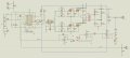
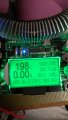
I have designed a push-pull converter but i am running issues recently. Without load, I am able to read 340VDC as expected. As long as I include the load, voltage drops significantly. When I pull 100mA, the voltage drops to 310 V. When i pull 200mA,voltage drops to 270V. I have a feedback circuit but i don't know why it drops that much. it also works great on simulaton. I even changed the frequency but couldn't manage to read stable voltage under load.
 

Attachments

ronsimpson

Joined Oct 7, 2019
3,037
Look at other power supplies.
You have the TL494's error amp running with a gain of 50. I know you think the gain is higher.
Most supplies have most of the gain at the "U4A" spot and have the Vref there. Then at the TL494 the gain is low. Also most people have capacitors in the loop so the gain at DC is very high and the gain at high frequencies is low.
 

Thread Starter

myil

Joined May 2, 2020
145
Look at other power supplies.
You have the TL494's error amp running with a gain of 50. I know you think the gain is higher.
Most supplies have most of the gain at the "U4A" spot and have the Vref there. Then at the TL494 the gain is low. Also most people have capacitors in the loop so the gain at DC is very high and the gain at high frequencies is low.
Hi Ron simpson,
Sorry,I am a newbie on electronics. how do you calculate the gain? What does this number refer to?
 

ronsimpson

Joined Oct 7, 2019
3,037
It has been many years ago I used TL494s. (decades) (memory is not good) I think the voltage on pin-3 most change by 3 volts to go from 0% to 100% duty cycle. If the error amp has a gain of 100 then the voltage at the bottom of the voltage divider must change by 0.03V. ( 3V/100 )

To test my idea: Now 340v to 270v with load. Increase R21 from 100k to 220k and see if the voltage changes with load is 1/2 as much.
 

Thread Starter

myil

Joined May 2, 2020
145
It has been many years ago I used TL494s. (decades) (memory is not good) I think the voltage on pin-3 most change by 3 volts to go from 0% to 100% duty cycle. If the error amp has a gain of 100 then the voltage at the bottom of the voltage divider must change by 0.03V. ( 3V/100 )

To test my idea: Now 340v to 270v with load. Increase R21 from 100k to 220k and see if the voltage changes with load is 1/2 as much.
Hi,
I don't have an electronic load that can handle 340V. I borrowed from university today to test it. I have an electronic load that can handle 180V. So I have adjusted my output to 150V.When I changed the resistor from 100k to 220k at pin 3, output voltage increased to 198V.
 

Attachments

Last edited:

ronsimpson

Joined Oct 7, 2019
3,037
I am confused.
Is this a "forward" power supply? or is it "flyback"? or ?
Please explain how it works?
It looks like when Q1,2 are on there is 12V across 1/2 of the transformer. When Q3,4 are on there is 12V across 1/2 of the transformer. I do not see how changing the duty cycle will effect the output voltage under load.
 
Last edited:

Thread Starter

myil

Joined May 2, 2020
145
I am confused.
Is this a "forward" power supply? or is it "flyback"? or ?
Please explain how it works?
It looks like when Q1,2 are on there is 12V across 1/2 of the transformer. When Q3,4 are on there is 12V across 1/2 of the transformer. I do not see how changing the duty cycle will effect the output voltage under load.
Hi ronsimpson,

Thanks for your help. It seems that I have solved the problem. It's my fault I couldn't put into account that supply cable could be the problem. I used almost a meter long cable which is around 1 - 1.5 ohm. Before input voltage reaches input terminal, voltage drop significantly. Let's say if I pull 5A from 12 V power supply, I loss 5-6 volts on the way. I am happy I have noticed that small detail. Thanks again :)

Regards
 
Last edited:
Top