 Facebook
 Google
 GitHub
 Linkedin
Hello,
i want to simulate a push pull converter to check my knowledge. So i came up with the circuit from the internet.
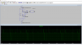
The green plot on the image is the voltage on the inductor which doesnt make much sene to me. What i was expecting is
a voltage on the inductor between -6V to 6V (PWM type of signal). Can anybody help me with this stuff?
What i also noticed is the voltage between the 2 capactiors is not 6V instead it seems like one capacitor is getting 9V and the other one only 3V. Why is that? The two capacitors form a voltage divider and they re equal....
Any hints or working simulations for me? Or a design tutorial with calculations?
I have also checked the pulses of the gates and they are 180° shifted in phase, so that only one of the transistors is turned on, then the other and the cycle repeats.
pleaseee thank u

i want to simulate a push pull converter to check my knowledge. So i came up with the circuit from the internet.
The green plot on the image is the voltage on the inductor which doesnt make much sene to me. What i was expecting is
a voltage on the inductor between -6V to 6V (PWM type of signal). Can anybody help me with this stuff?
What i also noticed is the voltage between the 2 capactiors is not 6V instead it seems like one capacitor is getting 9V and the other one only 3V. Why is that? The two capacitors form a voltage divider and they re equal....
Any hints or working simulations for me? Or a design tutorial with calculations?
I have also checked the pulses of the gates and they are 180° shifted in phase, so that only one of the transistors is turned on, then the other and the cycle repeats.
pleaseee thank u
Attachments
-
 56.4 KB Views: 51


