Purposes of these diodes in a circuit

LadySpark

Joined Feb 7, 2024
194
What do you mean "The ESD diodes are invisible to the circuit and do not play in any role in the operation of it."? member "Panic Mode" made extensive analysis and explanation of them in earlier messages in this thread.
Sorry to be blunt. But they are not part of the normal operation of the circuit, and what is the real reason for starting a thread if you are not going to listen to anyone's explanation of input protection diodes. Panic mode just went into detail on the not normal instance the diodes were design to handle: excessive voltage input. Which isn't normal operation. So what is suppose to connect to the input? I bet it doesn't even go near 8V anyways.
 

Thread Starter

Gpand

Joined Dec 11, 2023
105
Sorry to be blunt. But they are not part of the normal operation of the circuit, and what is the real reason for starting a thread if you are not going to listen to anyone's explanation of input protection diodes. Panic mode just went into detail on the not normal instance the diodes were design to handle: excessive voltage input. Which isn't normal operation. So what is suppose to connect to the input? I bet it doesn't even go near 8V anyways.
Ah ok. Diodes not forever visible but work during emergency. So its like they shared the same resistor 4.99k Ohms (working like a double agent). Input voltage is differential 10uV (microvolt), 1000Hz). Can it go directly to the AMP01 without the LF412 if the source impedance wont go above 10k ohm?
 

LadySpark

Joined Feb 7, 2024
194
Can it go directly to the AMP01 without the LF412 if the source impedance wont go above 10k ohm?
once the diode conducts, it shunts to the power supply rail, AMP01 IC isn't effected. You have the power drawn for the AMP01 instead of the signal path.
 

Thread Starter

Gpand

Joined Dec 11, 2023
105
once the diode conducts, it shunts to the power supply rail, AMP01 IC isn't effected. You have the power drawn for the AMP01 instead of the signal path.
What I mean to say is. Can the input biopotential signal of 10uV go directly to the AMP01 without needing the LF412 that conditions the signal. We are not talking about diodes conducting or ESD anymore. I need to eliminate the LF412 and have the input signal go directly to the AMP01. Is this possible?
 
according to one person:

"The Lf412 is a JFET input amplofier and as such has very high impedance, very low bias current and very low current noise. This allows it to have consistent performance even with a very high source impedance. This is why it is used as the input stage.

The AMP01 has more bias current and more current noise. These will limit performance and introduce errors and noise with a high impedance signal source. With the problems that come with modifying an existing circuit which has been factory trimmed for precision, I don't think a major modification like bypassing the input stage is going to be a good Idea.The BF412 in the BMA-200 acts as a pre-amplifier with gain of 2 and very high input impedance. It also provides trimming for CMRR and DC offset. Due to its near infinite input impedance and very low bias current, it has near zero current noise, so is ideal for buffering very high impedance signal sources."

"

If you want to reanalyse your amplifier to see what changing various components makes then, I think main noise sources in the signal path are:
Source resistance (e.g. 10 kOhm)
2x 5k protection resistors
2x op amps (20 nV/sqrt Hz for the original LF412)
Instrumentation amp (5 nV/sqrt Hz for the AMP01).

You are interested in a bandwidth of 1 kHz:
So the calculation becomes:
10k Source resistance: 0.13 * Sqrt (10000) * Sqrt (BW) = 411 nV rms
2x 5k Protection resistors: Sqrt(2) * 0.13 * Sqrt (5000) * Sqrt (BW) = 411 nV rms
2x OP amps: Sqrt(2) * 20 * Sqrt (BW) = 894 nV rms
I amp: 5 * Sqrt (BW) = 158 nV rms

The noise powers sum:
Total = Sqrt (411 ^2 + 411 ^2 + 894 ^2 + 158 ^2) = 1078 nV rms"
It is still an odd design and putting in a preamplifier before the IA is just making things harder to get right. But I am unaware of the circumstances of the design so maybe there is a reason for these things. It is much easier to critique than it is to design.
So you have everything you need now. Go for it and good luck.
 

Thread Starter

Gpand

Joined Dec 11, 2023
105
It is still an odd design and putting in a preamplifier before the IA is just making things harder to get right. But I am unaware of the circumstances of the design so maybe there is a reason for these things. It is much easier to critique than it is to design.
So you have everything you need now. Go for it and good luck.
No. The BMA-200 is quite noisy with 3.7356uV peak to peak even if I replaced the LF412 with OPA2132P and even assuming source impedance of zero instead of 10k Ohm (see computations below). It would be noisy for input signal of 10uV, 1000Hz. Therefore I'd scrap it and get the INA849 with incredible 1nV/Sqrt (Hz). Do you know any existing biopotential equipment that uses the INA849? What other 1nV/Sqrt (Hz) do you know? If not. I have to replace the LF412/OPA2132P and AMP01 in my existng BMA wth the INA849 by rewiring the socket and putting another socket on top and then the INA849. At least I have the chassis, input connectors, power supply etc. which would be difficult to fabricate from scratch. For shielding. I'd just make a bench size Faraday Cage for emi and interference protection.

main noise sources in the signal path for BMA-200 with OPA2132p are:
Source resistance (e.g. 10 kOhm)
2x 5k protection resistors
2x op amps (8 nV/sqrt Hz for the the OPA2132P)
Instrumentation amp (5 nV/sqrt Hz for the AMP01).

For bandwidth of 1 kHz:
So the calculation becomes:
10k Source resistance: 0.13 * Sqrt (10000) * Sqrt (BW) = 411 nV rms
2x 5k Protection resistors: Sqrt(2) * 0.13 * Sqrt (5000) * Sqrt (BW) = 411 nV rms
2x OP amps: Sqrt(2) * 8 * Sqrt (BW) = 357 nV rms
I amp: 5 * Sqrt (BW) = 158 nV rms

The noise powers sum:
Total = Sqrt (411 ^2 + 411 ^2 + 357 ^2 + 158 ^2) =
= Sqrt (168,921 + 168,921 + 127449 + 24,964)
= Sqrt (659,176)
= 812 nV rms = 0.812uV rms x 6.6 = 5.3592uV peak to peak

Without source impedance of 10k Ohm.
Total noise = 566.83nV = 0.566uV rms x 6.6 = 3.7356uV peak to peak


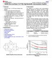
INA849 Ultra-Low-Noise (1 nV/√Hz), High-Bandwidth, Instrumentation Amplifier datasheet (Rev. B)

ina849.jpg
 
Last edited:
No. The BMA-200 is quite noisy with 3.7356uV peak to peak even if I replaced the LF412 with OPA2132P and even assuming source impedance of zero instead of 10k Ohm (see computations below). It would be noisy for input signal of 10uV, 1000Hz. Therefore I'd scrap it and get the INA849 with incredible 1nV/Sqrt (Hz). Do you know any existing biopotential equipment that uses the INA849? What other 1nV/Sqrt (Hz) do you know? If not. I have to replace the LF412/OPA2132P and AMP01 in my existng BMA wth the INA849 by rewiring the socket and putting another socket on top and then the INA849. At least I have the chassis, input connectors, power supply etc. which would be difficult to fabricate from scratch. For shielding. I'd just make a bench size Faraday Cage for emi and interference protection.

main noise sources in the signal path for BMA-200 with OPA2132p are:
Source resistance (e.g. 10 kOhm)
2x 5k protection resistors
2x op amps (8 nV/sqrt Hz for the the OPA2132P)
Instrumentation amp (5 nV/sqrt Hz for the AMP01).

For bandwidth of 1 kHz:
So the calculation becomes:
10k Source resistance: 0.13 * Sqrt (10000) * Sqrt (BW) = 411 nV rms
2x 5k Protection resistors: Sqrt(2) * 0.13 * Sqrt (5000) * Sqrt (BW) = 411 nV rms
2x OP amps: Sqrt(2) * 8 * Sqrt (BW) = 357 nV rms
I amp: 5 * Sqrt (BW) = 158 nV rms

The noise powers sum:
Total = Sqrt (411 ^2 + 411 ^2 + 357 ^2 + 158 ^2) =
= Sqrt (168,921 + 168,921 + 127449 + 24,964)
= Sqrt (659,176)
= 812 nV rms = 0.812uV rms x 6.6 = 5.3592uV peak to peak

Without source impedance of 10k Ohm.
Total noise = 566.83nV = 0.566uV rms x 6.6 = 3.7356uV peak to peak


INA849 Ultra-Low-Noise (1 nV/√Hz), High-Bandwidth, Instrumentation Amplifier datasheet (Rev. B)

View attachment 318775
You have just answered your own question, or at least have an answer to the right question: your current input stage is wrong, how to fix it? Your answer: find the right IA. I am not saying the INA849 is the right IA, it may be, or maybe not. But your existing solution is not working out for you, so a new design (and starting with the right IA) is the way to go. See, you can do this. Go for it and remember all that you have picked up here about noise etc. If you can't do it right now, you will be able to do it by the time you have finished ;) We all have to start somewhere.

{edit}

I just did a search on "Instrumentation amp for EEG" and a TI E2E link came up with a post from someone doing something very similar to you:
https://www.google.com/url?sa=t&sou...4QFnoECBMQAQ&usg=AOvVaw38Ulx05271JVMCxDqub3yt
There are loads of little gems in there including the RLD (right leg drive) and how it can be used for EEG purposes. They are also using dry electrodes as I am guessing you want to do as well. Have a read. It starts with pointers to ECG technologies because it is similar bio sensing and although the signals for EEG are much smaller, the principles remain the same (unless the electrodes can be surgically applied of course, that would change everything). Because real engineers from TI who know about the topic they post on moderate the TI E2E forums you should find the signal to noise ratio in posts on those forums much better. :)
Understand that what you are trying to do is not a simple thing. It would challenge most any engineer, even experienced ones. The OP in that link talks about the sensitivity of the input and it picking up stray signals: "my foot being near a plug socket, my laptop charger throwing off noise, the fact i've built it on vero-board - which is touching my jumper - magically coupling it to my stereo ".
You may find very interesting times ahead in your project.
 
Last edited:

Thread Starter

Gpand

Joined Dec 11, 2023
105
You have just answered your own question, or at least have an answer to the right question: your current input stage is wrong, how to fix it? Your answer: find the right IA. I am not saying the INA849 is the right IA, it may be, or maybe not. But your existing solution is not working out for you, so a new design (and starting with the right IA) is the way to go. See, you can do this. Go for it and remember all that you have picked up here about noise etc. If you can't do it right now, you will be able to do it by the time you have finished ;) We all have to start somewhere.

{edit}

I just did a search on "Instrumentation amp for EEG" and a TI E2E link came up with a post from someone doing something very similar to you:
https://www.google.com/url?sa=t&sou...4QFnoECBMQAQ&usg=AOvVaw38Ulx05271JVMCxDqub3yt
There are loads of little gems in there including the RLD (right leg drive) and how it can be used for EEG purposes. They are also using dry electrodes as I am guessing you want to do as well. Have a read. It starts with pointers to ECG technologies because it is similar bio sensing and although the signals for EEG are much smaller, the principles remain the same (unless the electrodes can be surgically applied of course, that would change everything). Because real engineers from TI who know about the topic they post on moderate the TI E2E forums you should find the signal to noise ratio in posts on those forums much better. :)
Understand that what you are trying to do is not a simple thing. It would challenge most any engineer, even experienced ones. The OP in that link talks about the sensitivity of the input and it picking up stray signals: "my foot being near a plug socket, my laptop charger throwing off noise, the fact i've built it on vero-board - which is touching my jumper - magically coupling it to my stereo ".
You may find very interesting times ahead in your project.

We don't have time to build a new one from scratch. We will just spend our time on measurements and experiments and using learning Matcad for signal analysis. So we will just buy existing one. Which product has 1nV/Sqrt (Hz) amplifier?
 
We don't have time to build a new one from scratch. We will just spend our time on measurements and experiments and using learning Matcad for signal analysis. So we will just buy existing one. Which product has 1nV/Sqrt (Hz) amplifier?
Commercial amplifiers don't tend to be specified that way.
 
Top