Facebook
 Google
 GitHub
 Linkedin
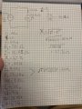
I see a lot of reference to a purely inductive circuit being one that only has an inductive load. But in practice, does the resistance of the coil itself make it an R-C circuit? I was recently analyzing a real circuit with no other load than an AC relay coil, and found measurable resistance in the coil (70.1 ohms) itself, and ended up with an angle Theta of 67.6 degrees.
Are there inductive circuits in the real world that have a corresponding phase shift that approaches 90 degrees? Searching the forum didn't result in any conclusive answer.
Are there inductive circuits in the real world that have a corresponding phase shift that approaches 90 degrees? Searching the forum didn't result in any conclusive answer.