Pulsing an eTec Outboard Fuel Injector

Alec_t

Joined Sep 17, 2013
15,134
Did you guys watch the video or look at the Alec's first link? Alec you should have since you posted both.
I did both. I am well aware that the injector is unconventional and operates on a voice-coil principle. In normal use in an engine, or in testing, dual-polarity pulses are fully justified. The point at issue is whether dual-polarity is needed or advantageous when the injector is simply being cleaned.
 
Last edited:

wayneh

Joined Sep 9, 2010
18,130
We don't know the details yet but perhaps the push-pull pulses could be produced by a half-bridge and a capacitor, as opposed to a full H-bridge. I used the circuit below to drive an inverter coil for my EL tape project. It could not provide a sustained pulse in either direction and the capacitor size for this application might be impractical if the pulse time is "long". Just a thought.

C6 is the cap and L1 would be the injector in this scenario. M1 and M2 alternate the voltage on C6 and thus the current in L1.
The injector would be isolated from the power - no DC - which is useful.

Screen Shot 2020-04-18 at 12.11.01 PM.png
 

Alec_t

Joined Sep 17, 2013
15,134
Interesting circuit, but the posted scope waveform shows an interval between the forward pulse and the reverse pulse. Whether or not that is essential is unknown. Methinks C6 would have to be impractically large, since coil current can be ~ 20A apparently.
 

shortbus

Joined Sep 30, 2009
10,049
I did both. I am well aware that the injector is unconventional and operates on a voice-coil principle. In normal use in an engine, or in testing, dual-polarity pulses are fully justified. The point at issue is whether dual-polarity is needed or advantageous when the injector is simply being cleaned.
The part needing cleaned NEEDs the full pulse of the coil, to overcome the pintle spring. Because the pintle is what is usually the clogged part. The injector is already being supplied with around 45 - 50 PSI fuel then the pulse forces what their calling a "poppet valve", actually a piston in a cylinder, to add more pressure to open the pintle. The video during the first 7 minutes explains it all.

I'm thinking that of the two pulses he got on his scope, the long one is what pulls the coil back, the short one is the one going forward . The forward movement needs to be the shorter one to meter the amount of fuel injected. And as RPMs and load increase the short pulse is made longer.
 

wayneh

Joined Sep 9, 2010
18,130
Interesting circuit, but the posted scope waveform shows an interval between the forward pulse and the reverse pulse. Whether or not that is essential is unknown. Methinks C6 would have to be impractically large, since coil current can be ~ 20A apparently.
The pause would not be a problem because the cap would stop the current after the pulse drains it (or charges it). But yeah, you’re not going to get the same profile. Open and close, yes. Hold open? No.
 

Alec_t

Joined Sep 17, 2013
15,134
I'm thinking that of the two pulses he got on his scope, the long one is what pulls the coil back, the short one is the one going forward . The forward movement needs to be the shorter one to meter the amount of fuel injected.
The scope pulses relate to the cleaning mode. In that mode I doubt the 'fuel' (or whatever liquid is used) is being metered. At the moment we simply can't be certain what's what.
You seem sure that permanent magnetisation won't be a problem. That's probably the case, but I was merely hypothesising that it might be. It clearly depends on the materials this beast is constructed from. Do you have any reliable technical data you can share? Google isn't turning up much of use.
 

shortbus

Joined Sep 30, 2009
10,049
Do you have any reliable technical data you can share? Google isn't turning up much of use.
May be look at Bombardier (BRP) for more information. They use the same Etec on many of their products.

Personally I would think like I said earlier a 50-50 square wave would be best for cleaning in this case, and around 24 volts. But just my guess at this. Stop and think, these injectors have to work at a 12V battery voltage as they are cranking over when starting. I still think though the 55V is not a reliable voltage in the actual running of the motor, maybe for a cleaning machine but not a running motor. At the replacement cost of these injectors I'd want to error on the low side myself.
 

wayneh

Joined Sep 9, 2010
18,130
May be look at Bombardier (BRP) for more information. They use the same Etec on many of their products.

Personally I would think like I said earlier a 50-50 square wave would be best for cleaning in this case, and around 24 volts. But just my guess at this. Stop and think, these injectors have to work at a 12V battery voltage as they are cranking over when starting. I still think though the 55V is not a reliable voltage in the actual running of the motor, maybe for a cleaning machine but not a running motor. At the replacement cost of these injectors I'd want to error on the low side myself.
Not sure about the square wave but otherwise agreed. There's no need to slam these thing around like you're running at 6,000rpm. You just need to open and close. Until the engine starts, you only have 12V and that should be enough.
 

Alec_t

Joined Sep 17, 2013
15,134
You just need to open and close. Until the engine starts, you only have 12V and that should be enough.
Seems reasonable. Considering that in the cleaning process the injector is working against atmospheric pressure and not against high cylinder pressure, I'd guess a voltage much lower than 55V would be adequate for opening it.
 

shortbus

Joined Sep 30, 2009
10,049
You would also need the electric fuel pump that they use in the vehicle. The fuel pump would pump the cleaning fluid, and the pump need to make ~45 PSI to open the check valve that fills the fuel chamber that supply's the pintle. These direct injection injectors have to overcome the combustion chamber pressures.
 

Alec_t

Joined Sep 17, 2013
15,134
The fuel pump would pump the cleaning fluid, and the pump need to make ~45 PSI to open the check valve that fills the fuel chamber that supply's the pintle.
In this video it looks as though the injector gets cleaned minus its spray nozzle, poppet and filter, and without the cleaning fluid being pumped.
 

Alec_t

Joined Sep 17, 2013
15,134
I guess your box provides options for pulse width and repetition rate in the testing process, but does it do so in the cleaning process?
 

shortbus

Joined Sep 30, 2009
10,049
In this video it looks as though the injector gets cleaned minus its spray nozzle, poppet and filter, and without the cleaning fluid being pumped.
How will that clean the actual injector? That's only cleaning the fuel chamber, like this guy shows.

This video shows how big it is

The stuff they seem to get built up in them looks like what is called "cokeing", overheated but not burned petroleum residue. Those injectors needed to be water cooled, with a pump that ran after the motor shut off, like the first electric cooling fans in cars.
 

Thread Starter

InjectorService

Joined Apr 11, 2020
35
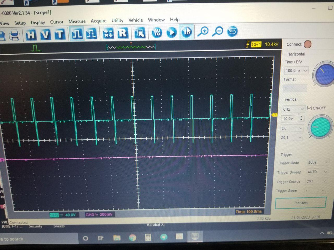
Wow I can't believe how far this thread has gone without a single post from me. It really shows what kind of guys you are, obviously more than willing to help. Here is some scoped images of the waveform that is made during my machine's cleaning process. You can see that it is definitely reversing the signal. It looks to be operating at ~14Hz, with a positive pulse width of 7.37ms. For some reason I can't get the negative pulse width to read but it looks around 2ms judging by the scope picture.

Also, you can see the voltage is the same as the converter itself - 48V. I think in the last picture I had my scope settings all messed up, but I am confident I got it right now.

NOW, I don't have the amp reading or waveform from actually running the injector. I do have an injector I can hook up and take the reading with, but my amp clamp is currently dead and I need batteries.

ALSO - Be a little bit careful with what you all read and hear on the internet about these injectors, there is a LOT of misconception and misinformation about them.


Thread Starter

InjectorService

Joined Apr 11, 2020
35
Also Ill get you a video of the cleaning process on the eTec injectors next time I run a set. They sit in an ultrasonic bath, with the pintle facing straight up (although the pintle has been removed). The fluid is not pumped in any way other than the injector itself. It does pump quite a bit on it's own however, the spray can go about 10" above the injector.
 

Alec_t

Joined Sep 17, 2013
15,134
Nice scope pics. Now the numbers look more believable. (Actually the previous numbers made sense, once I realised you had the probe attenuation of 20x but the scope set to 10000x :) ).
Just curious as to why the pulse edges are slanted a bit in the second pic but vertical in the third pic?
As asked previously, does your box have user-selectable pulse widths for the cleaning process, or is it one size fits all? Would it be an advantage to have selectable pulse widths to cope with different models of the injector?
For a DIY pulser, a micro-controller is an obvious choice to do all the timing and sequencing for multiple injectors, but if you want to go old-school and are interested I have designed a pulser/sequencer circuit using half-a dozen CD40xx ICs as a starting point.
 

shortbus

Joined Sep 30, 2009
10,049
Also Ill get you a video of the cleaning process on the eTec injectors next time I run a set. They sit in an ultrasonic bath, with the pintle facing straight up (although the pintle has been removed). The fluid is not pumped in any way other than the injector itself. It does pump quite a bit on it's own however, the spray can go about 10" above the injector.
Do you also take them apart to manually scrape out the residue? Before a sonic cleaning.
 

Thread Starter

InjectorService

Joined Apr 11, 2020
35
Nice scope pics. Now the numbers look more believable. (Actually the previous numbers made sense, once I realised you had the probe attenuation of 20x but the scope set to 10000x :) ).
Just curious as to why the pulse edges are slanted a bit in the second pic but vertical in the third pic?
As asked previously, does your box have user-selectable pulse widths for the cleaning process, or is it one size fits all? Would it be an advantage to have selectable pulse widths to cope with different models of the injector?
For a DIY pulser, a micro-controller is an obvious choice to do all the timing and sequencing for multiple injectors, but if you want to go old-school and are interested I have designed a pulser/sequencer circuit using half-a dozen CD40xx ICs as a starting point.
I'm thinking the edges might be sloped due to the quality of software/scope and I just paused it at a bad spot. When it was running it bounced around a little but was mostly completely vertical.

For this box I don't need selectable pulse widths. I only care to replicate this waveform. The actual test bench I use has the option to set various waveforms and RPMs, and I'm not looking to replicate that right now.

As far as the electronics go, it doesn't really matter which way we go (micro-controller or CD40xx IC). I guess my question is does the microcontroller need to be programmed? I think they are using a microcontroller on my current system, but I will follow your suggestions.
 
Top