Pulser input to a timer relay signal input not shutting down.

LesJones

Joined Jan 8, 2017
4,509
datona, First as you have not yet supplied a schematic of how things are connected I have assumed that the pulser output is a switch contact with one side of the switch connected to a +12 volt supply and the other side of the switch is the pulse output. Is this assumption correct ? Are you saying that when you tried one of the suggested circuits it causer the 12 volt supply to the pulser to drop to zero ? Even if your capacitor was short circuit none of the three suggested circuits (You did not say which of the three circuits you tried.) would draw much over 1 mA. I find it difficult to believe an extra load of 1 mA could losd the 12 volt power supply to zero volts.

Les.
 

Thread Starter

daytona

Joined Jan 15, 2021
41
We are aware that when the pulser stops, sometimes its output remains at 12v. The purpose of the differentiator is to overcome this. Each time the pulser output "rises" from 0v to 12v, the differentiator circuit outputs a short pulse that rises, and after a short duration, quickly falls. So...with the differentiator circuit connected between the pulser and timer, even though the pulser output may stop at 12V, the timer "S" terminal will see 0v. When the Pulser begins to "pulse" again, the differentiator will output a rising pulse on the first rise of the pulser output and trigger the timer.

But....for this to work reliably, specifics on the Pulser output waveform and Timer input waveform is required so that the differentiator circuit can properly "condition" the output signal sent to the Timer.

Hope that helps....
Thanks I will work on it after the customer goes home or boss will have to hire an EE. I am the Quality manager who knows more about electronics than our ME's because we lost our EE
 

Thread Starter

daytona

Joined Jan 15, 2021
41
datona, First as you have not yet supplied a schematic of how things are connected I have assumed that the pulser output is a switch contact with one side of the switch connected to a +12 volt supply and the other side of the switch is the pulse output. Is this assumption correct ? Are you saying that when you tried one of the suggested circuits it causer the 12 volt supply to the pulser to drop to zero ? Even if your capacitor was short circuit none of the three suggested circuits (You did not say which of the three circuits you tried.) would draw much over 1 mA. I find it difficult to believe an extra load of 1 mA could losd the 12 volt power supply to zero volts.

Les.
I will draw a circuit and take a picture. I have a phone cord today. The big circuit is very complicated and takes a month to understand. I will do that after I get ready for the customer. There are about 8 people coming to see the product tomorrow and Thursday
 

Thread Starter

daytona

Joined Jan 15, 2021
41
Here is the description of what I need to do. We want to keep it to electro-mechanical as much as possible.
Objective: when flow stops for 15 seconds or more the pump needs to shut down.
Situation: This is a fuel pumping situation with a typical gas station nozzle and holster. when the nozzle is removed the pump starts running. The customer wants to give the operator 60 seconds to squeeze the trigger and start pumping fuel. If the fuel stops for any reason (out of fuel, clog, valve not open) they want it to cut off the pump motor.
SOLUTION: If you have a solution that is not using the components I have listed I am open to any solution. Boss doesnt want to use a flow switch in the fuel line but that may be the best solution with a delay timer. I will attach what I have tried and I left the connection from the pulser to "S" on the Schneider disconnected

DETAILS I TRIED: The safe relay detects when the nozzle is out and powers the c3 brand timer relay which starts the pump motor relay. I set the c3 to stay on for 60 seconds. The Schneider 821TD10H-UNI Time delay relay is supposed to keep power on the motor relay until flow stops for 15 sec. I have tried the Off delay with "s" break and I tried Retriggerable one shot with "s" relay is set to 15 sec. When the "S" sees a pulse it starts the timer again so it never actually starts the countdown sequence until pulses stop. What happens is the 12vdc output from an electro-mechanical pulser that runs to a digital counter and also runs to a digital timer relay. I need the timer to count down when pulses stop. What is happening is that the timer counts down perfectly when the pulser stops pulsing on the off pulse (or between pulses) but fails to count down when the pulser stops on a 12 Vdc pulse. I have tried to pull the 12vdc down using cap, diode and resistor, but perhaps I wired them incorrectly.
One thing I don't like is that we have the neutral for 120Vac and the 12Vdc ground connected.
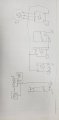
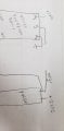
Once again if you can think of a solution without a complicated circuit board I would appreciate it. I am taking tomorrow off bc I have worked too many hours. customer was pleased but demands I fix the issue.20210304_160747.jpg20210304_160757.jpg
 

sghioto

Joined Dec 31, 2017
8,686
but fails to count down when the pulser stops on a 12 Vdc pulse.
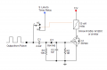
This circuit will eliminate that problem.
The relay will energize with the first pulse from the Pulser and connect the S line to the Timer Relay.
After the last pulse is received whether it's zero or stuck on 12 volts the relay will drop out after about 2 seconds disconnecting the S line from the Timer Relay which will start the 15 second delay.
Set Timer Relay in the OFF DELAY mode "D".
1615398635702.png
 
Last edited:

LesJones

Joined Jan 8, 2017
4,509
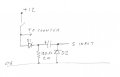
I think sghioto's circuit in post #25 is about the simplest without having full details of the inputs circuits of digital counter and the Schneider 821TD10H-UNI Time delay and the output circuit of the pulser. The original circuit that I suggested would not work as the Schneider 821TD10H-UNI Time delay requires a 50 mS minimum pulse duration. I think there is a small error in your schematic. I think you have missed a link between the "SAFE RELAY" 120V AC output and the common relay output connection on the Schneider 821TD10H-UNI Time delay. Here is a circuit with less components but you will have to experiment with the capacitor as we don't know the input current of the 821TD10H-UNI Time delay.
050321.jpg
D1 is to prevent the discharging of the capacitor from slowing down the falling edge of the pulse to the counter, D2 is to prevent a negative pulse on the S input to the 821TD10H-UNI Time delay. I think you will need a fairly high value capacitor. I suggest starting with about 100 uF (25 volt working.)
I don't think the 12 volt negative being connected to 120v neutral will be a problem.

Les.
 

Thread Starter

daytona

Joined Jan 15, 2021
41
I think sghioto's circuit in post #25 is about the simplest without having full details of the inputs circuits of digital counter and the Schneider 821TD10H-UNI Time delay and the output circuit of the pulser. The original circuit that I suggested would not work as the Schneider 821TD10H-UNI Time delay requires a 50 mS minimum pulse duration. I think there is a small error in your schematic. I think you have missed a link between the "SAFE RELAY" 120V AC output and the common relay output connection on the Schneider 821TD10H-UNI Time delay. Here is a circuit with less components but you will have to experiment with the capacitor as we don't know the input current of the 821TD10H-UNI Time delay.
View attachment 232137
D1 is to prevent the discharging of the capacitor from slowing down the falling edge of the pulse to the counter, D2 is to prevent a negative pulse on the S input to the 821TD10H-UNI Time delay. I think you will need a fairly high value capacitor. I suggest starting with about 100 uF (25 volt working.)
I don't think the 12 volt negative being connected to 120v neutral will be a problem.

Les.
You are correct in my haste before I took off, I left off the wire to the common. Both commons get the same input. I will try the circuit and see if I can find what works.
 

LesJones

Joined Jan 8, 2017
4,509
Can you measure the current into the "S" terminal on the timer with 12 volts connected to it ? This could help to work out component values. I have noticed when I found the datasheet for the 821TD10H-UNI Time delay that there is a green LED on it to indicate an input to the "S" terminal. this may save you time working on it as you will be able to see if it's input is being pulsed without having to wait to see it the timer times out.

Les.
 

Thread Starter

daytona

Joined Jan 15, 2021
41
Can you measure the current into the "S" terminal on the timer with 12 volts connected to it ? This could help to work out component values. I have noticed when I found the datasheet for the 821TD10H-UNI Time delay that there is a green LED on it to indicate an input to the "S" terminal. this may save you time working on it as you will be able to see if it's input is being pulsed without having to wait to see it the timer times out.

Les.
LES, I can't get time on the unit right now. They tore it apart and haven't fixed the generator yet. If I can't get time on the unit i may try to test the pulser and timer on the bench. I assume that the pulser puts out 12 Vdc
 

Thread Starter

daytona

Joined Jan 15, 2021
41
Can the counter output a pulse when it counts?
On the bench The current from a 12Vdc power supply to "S" is .88 mA. No the counter can't output it's own pulse It has rs232 capability but that is only for programming. What I am doing is running the pulser signal to the timer and to 2 different counters. One is resetable and the other is non resetable.
 

Ya’akov

Joined Jan 27, 2019
10,263
On the bench The current from a 12Vdc power supply to "S" is .88 mA. No the counter can't output it's own pulse It has rs232 capability but that is only for programming. What I am doing is running the pulser signal to the timer and to 2 different counters. One is resetable and the other is non resetable.
That’s a shame, and edge detecting pulse generator as a buffer between the problematic pulse and the timer would be a good solution.
 

Thread Starter

daytona

Joined Jan 15, 2021
41
Can you measure the current into the "S" terminal on the timer with 12 volts connected to it ? This could help to work out component values. I have noticed when I found the datasheet for the 821TD10H-UNI Time delay that there is a green LED on it to indicate an input to the "S" terminal. this may save you time working on it as you will be able to see if it's input is being pulsed without having to wait to see it the timer times out.

Les.
On the bench The current from a 12Vdc power supply to "S" is .88 mA. My boss wants to know if any of you do consulting work. He may need help in the future. Plus he hates to get free advise. He likes to pay for what he gets.

Quote
 

LesJones

Joined Jan 8, 2017
4,509
I don't do consulting work. I enjoy the freedom of being retired too much. It is possible some members may be interested but bear in mind the members are scattered all around the world. I think if anyone is interested you would need someone from your country (Which I would guess to be the US.). Thanks for measuring the input current of the timer. Could you measure the output voltage of the pulser with it's output still connected to the rest of the unit both when it is stopped on a pulse and when it is not on a pulse. This will help us to know if it's output is just a set of contacts. (I am assuming that you don't have an oscilloscope which would save you from having to stop the pulser on a pulse. Am I correct in assuming the pulser and counter are to measure the volume of liquid dispensed ? (This is just out of interest. It does not change any of the ideas for a solution to the problem.)

Les
 

Thread Starter

daytona

Joined Jan 15, 2021
41
I don't do consulting work. I enjoy the freedom of being retired too much. It is possible some members may be interested but bear in mind the members are scattered all around the world. I think if anyone is interested you would need someone from your country (Which I would guess to be the US.). Thanks for measuring the input current of the timer. Could you measure the output voltage of the pulser with it's output still connected to the rest of the unit both when it is stopped on a pulse and when it is not on a pulse. This will help us to know if it's output is just a set of contacts. (I am assuming that you don't have an oscilloscope which would save you from having to stop the pulser on a pulse. Am I correct in assuming the pulser and counter are to measure the volume of liquid dispensed ? (This is just out of interest. It does not change any of the ideas for a solution to the problem.)

Les
I will measure the pulser output tomorrow they made me take it off for the customer. I am not only from USA even better TEXAS.
 

LesJones

Joined Jan 8, 2017
4,509
I have been reading through the thread again to see if I could find any more information about the pulser output and the timer input. I did not find any more information but I did notice that there is another possible problem. The maximum pulse rate is 20 hz. This has a period of 50 mS, The datashhet on the timer says it's minimum pulse duration is 50 mS A pulse train with a period of 50 mS can't have a pulse duration of 50 mS. If the duty cycle of the pulse train was 50% then when it was at a frequency of 20 hz the pulse duration would only be 25 mS. I don't think this has anything to do with your problem as it would show up as the timer not seeing pulses near the maximum frequency input. I think the circuit I posted in post #26 would work but I think sghioto's circuit in post #25 is better as that is actually doing the missing pulse detection. The relay in that circuit only needs to be a very small relay as the contacts will only be switching a current of about 1 mA. Also the 2N7000 is only capable of switching a current of 280 mA for the relay coil. There are small relays that are suitable whose 12 volt coil only requires about 20 mA.

Les.
 

Thread Starter

daytona

Joined Jan 15, 2021
41
I have been reading through the thread again to see if I could find any more information about the pulser output and the timer input. I did not find any more information but I did notice that there is another possible problem. The maximum pulse rate is 20 hz. This has a period of 50 mS, The datashhet on the timer says it's minimum pulse duration is 50 mS A pulse train with a period of 50 mS can't have a pulse duration of 50 mS. If the duty cycle of the pulse train was 50% then when it was at a frequency of 20 hz the pulse duration would only be 25 mS. I don't think this has anything to do with your problem as it would show up as the timer not seeing pulses near the maximum frequency input. I think the circuit I posted in post #26 would work but I think sghioto's circuit in post #25 is better as that is actually doing the missing pulse detection. The relay in that circuit only needs to be a very small relay as the contacts will only be switching a current of about 1 mA. Also the 2N7000 is only capable of switching a current of 280 mA for the relay coil. There are small relays that are suitable whose 12 volt coil only requires about 20 mA.

Les.
The boss hired an electronic engineer and he made a circuit board. We spent the whole day only to find that something somewhere puts an osolation or repeated pulse with sharp pulse then decay and a cycle of 2 mil sec period. He brought an oscope. After several seconds the pulse goes away. I am off the project for a week so the tech can test the other functions. Thanks for the help.
 

Thread Starter

daytona

Joined Jan 15, 2021
41
I have been reading through the thread again to see if I could find any more information about the pulser output and the timer input. I did not find any more information but I did notice that there is another possible problem. The maximum pulse rate is 20 hz. This has a period of 50 mS, The datashhet on the timer says it's minimum pulse duration is 50 mS A pulse train with a period of 50 mS can't have a pulse duration of 50 mS. If the duty cycle of the pulse train was 50% then when it was at a frequency of 20 hz the pulse duration would only be 25 mS. I don't think this has anything to do with your problem as it would show up as the timer not seeing pulses near the maximum frequency input. I think the circuit I posted in post #26 would work but I think sghioto's circuit in post #25 is better as that is actually doing the missing pulse detection. The relay in that circuit only needs to be a very small relay as the contacts will only be switching a current of about 1 mA. Also the 2N7000 is only capable of switching a current of 280 mA for the relay coil. There are small relays that are suitable whose 12 volt coil only requires about 20 mA.

Les.
Thanks if the boss will let me, I will let the electronic guy know both solutions and see what he comes up with. The customer was pleased with the pumping unit but the no flow cut off has to be fixed. I will attach a diagram of what the electronic guy comes up with and will post the final solution when we get it. I will be on vacation next week but will jump on it next month.
 

Thread Starter

daytona

Joined Jan 15, 2021
41
This circuit will eliminate that problem.
The relay will energize with the first pulse from the Pulser and connect the S line to the Timer Relay.
After the last pulse is received whether it's zero or stuck on 12 volts the relay will drop out after about 2 seconds disconnecting the S line from the Timer Relay which will start the 15 second delay.
Set Timer Relay in the OFF DELAY mode "D".
View attachment 232418
Thanks if the boss will let me, I will let the electronic guy know both solutions and see what he comes up with. The customer was pleased with the pumping unit but the no flow cut off has to be fixed. I will attach a diagram of what the electronic guy comes up with and will post the final solution when we get it. I will be on vacation next week but will jump on it next month.
 
Top