Pulse to Analog Circuit Help

Thread Starter

Jordan Clark

Joined Mar 16, 2018
3
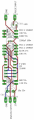
I pulled this circuit from a board in my boat. It takes the tach pulse signal and converts it to an analog value. The inputs are at the top, only the tach signal and gnd. The outputs are at the bottom gnd, 0 - ~5v analog out, and 12v. This circuit is good for up to I think about 5000-5500 rpm which is all the boat engine will do. What would I need to change to make it capable of reading up to 10000 rpm on a v8 engine which equates to around 667 pulses per second?
 

Attachments

bertus

Joined Apr 5, 2008
22,925
Hello,

Do you have the schematic that belongs to the given PCB drawing?
That is much easier to read and possible to adopt.

Bertus
 

Thread Starter

Jordan Clark

Joined Mar 16, 2018
3
I don't. I just drew that up by looking at the board and finding where the traces went. I could possibly try to draw the schematic up, however, every time I do a schematic it tends to be more jumbled up than the board itself.
 

crutschow

Joined Mar 14, 2008
38,508
I don't. I just drew that up by looking at the board and finding where the traces went. I could possibly try to draw the schematic up, however, every time I do a schematic it tends to be more jumbled up than the board itself.
Yes.
The usual method is to first draw a rats-nest schematic from the board, and then redraw it into a more conventional looking schematic that is easier to understood.
Sounds like a good exercise for you. ;)
With a readable schematic you are likely to get more help.
 

wayneh

Joined Sep 9, 2010
18,104
FWIW, I think that circuit is just an RC low-pass filter on both the input and the output of the op-amp. Pulses are captured by the peak detector diodes, raise the average voltage on the input capacitor. The op-amp watches that voltage and puts a voltage on the output capacitor which powers the analog meter.

I suspect you could turn down the sensitivity by changing the initial resistive voltage divider. It would be fairly easy to test my hypothesis by jumpering another resistor onto that existing divider, to observe a change in the response to pulses.
 

sghioto

Joined Dec 31, 2017
8,634
From the PCB drawing I get this. Feel free to modify if you can see something I can't. Looks like a comparator as a pulse stretcher.
SG
EEE LM324 F toV.png
 
Last edited:
Top