Pull down resistor configuration

Thread Starter

plugnplay

Joined Mar 24, 2022
8
Hi all,

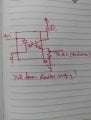
I am interfacing input to arduino with optocoupler. can anyone suggest the pull down resistor circuit with common emitter configuration. I have something in mind which i am attaching for ref. Please suggest better configuration.
(P.S.. I am new to design)

Thanks in advance.
 

Attachments

Papabravo

Joined Feb 24, 2006
21,226
Lots of questions for you to answer because you did not provide ANY relevant information.
  1. What voltage is resistor Rc connected to?
  2. What optocoupler are you using?
  3. What is the CTR of the optocoupler?
  4. Why are you using two resistors?
  5. What voltage are you μP inputs expecting?
  6. What is the diode current?
  7. What is driving the diode?
When you draw a schematic you should get in the habit of putting this kind of information on it so we don't have to drag it out of you.
 

Thread Starter

plugnplay

Joined Mar 24, 2022
8
Lots of questions for you to answer because you did not provide ANY relevant information.
  1. What voltage is resistor Rc connected to?
  2. What optocoupler are you using?
  3. What is the CTR of the optocoupler?
  4. Why are you using two resistors?
  5. What voltage are you μP inputs expecting?
  6. What is the diode current?
  7. What is driving the diode?
When you draw a schematic you should get in the habit of putting this kind of information on it so we don't have to drag it out of you.
Vcc= 5 VDC
Optocoupler=CNY74
CTR=50% to 600%
diode current= 60mA.
I am designing general purpose board with some input and outputs.
 

Papabravo

Joined Feb 24, 2006
21,226
Vcc= 5 VDC
Optocoupler=CNY74
CTR=50% to 600%
diode current= 60mA.
I am designing general purpose board with some input and outputs.
Since the opto will age over time and the CTR will get worse. I would start with a transistor current range of say 3mA-30mA.
This implies no more than 50 μA if the part is brand new and HOT at a CTR of 600% to a maximum of 6 mA if the part is old and the CTR is 50% There are a number of circuits that you can construct which will do this adaptation over time. You could also pick some intermediate point to design around and hope that you get no failures. That's terrible engineering and marginal economics.
 

Papabravo

Joined Feb 24, 2006
21,226
Here is a simulation of the CNY74 with various values for the CTR. Although the Igain parameter is related to the actual CTR, you should notice that CTR is not exactly constant. This works in simulation, but don't actually try this IRL.

1675549068839.png
 

Attachments

Ian0

Joined Aug 7, 2020
9,839
Theoretically, if both input and output supplies are the same voltage, the output pullup (or pulldown) resistor should be the input current limiting resistor divided by the CTR.
In practice make the output pullup larger than that. If you make it MUCH larger it will become slow (but that may not matter).
It will work at any input current from below 1mA to more than 20mA. More current = more noise immunity but slower response.
For really good noise immunity, use an H11L1, which has a built-in schmitt trigger and logic level outpu.
 
Top