Why don't you run the fan on Halfwave using a diode in series with the fan across the Transformer, the same for the other fan using the diode on the other half cycle.
Why don't you run the fan on Halfwave using a diode in series with the fan across the Transformer, the same for the other fan using the diode on the other half cycle.
Thank you for the idea. I am not familiar with those concepts. Where can I learn how to do that? (I also decided to go with just one larger fan - 330mA ). I surely must have been wrong about the current draw for the smaller fan.
Why don't you run the fan on Halfwave using a diode in series with the fan across the Transformer, the same for the other fan using the diode on the other half cycle.
I've got some 1N4004 diodes that are rated at 400V so I think those can work. How does this design know to supply the 12V to the fan rather than some other voltage?
It's the base-emitter junction that needs to be turned on, so the calculation is
\(R=\frac{V_{BE}}{I_{D1}}=\frac{0.7V}{9mA}=77.7\Omega\)
The closest standard 5% value would be 75 ohms.
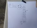
You're missing a connection dot on the cathode of C2 (critical) and the anode of C3 (cosmetic). The secondary voltage should be on the secondary, not by the switch. We don't wrap circuits like that. The preferred direction is left to right and top to bottom. There are exceptions to that rule, but this isn't one of them.
EDIT: 1N4745 is a 16V zener, so you're not understanding the circuit.
I gave this a try with the 1N4004. I have the following voltages (all with no load):
at anode of C2: 40V
at cathode of Zener: 39.9V
at anode of Zener: -1.8V
at pin 1 of L7812: -2.0V
When I added the fan, the Zener burned up. What am I doing wrong?
Sorry. I got things confused. I am using 1N4004, not Zener.
I remeasured. What is see now is the volts at cathode are inching up from about 300mV. When it gets to 400mV, it drops again. Cycle repeats.Same at pin 1 of the L7812.
You need to put a load on across the capacitor , say a 100 ohms resistor the voltage across it will be around 14 V, and the fan should be able to spin .
You need to put a load on across the capacitor , say a 100 ohms resistor the voltage across it will be around 14 V, and the fan should be able to spin .
I added a 100ohm resistor parallel to the cap. New results:
at anode of C2: 40V
at cathode of Zener: 40V
at anode of Zener: 39.2V
at cathode of cap: 39.2
at pin 1 of L7812: 39.2
at pin 3 of L7812: 3.5 (I assume it's in self-protect mode as 35V is it's max)
no spin
What am I doing wrong?
Thanks for all your patient help!
That regulator is going to be dissipating nearly 7 watts and will cook itself to death in short order. Are you familiar with what happens to an IC when you let the magic smoke out?
I double-checked the pinouts and I think I have that part right. I am only using one fan so, as far as I can tell, what I drew is similar to your post #25 for one fan.
 Facebook
 Google
 GitHub
 Linkedin