If you want 12 volts you set the power supply to give 12 volts. It should then give 12 volts (Or very close to 12 volts.) When you draw a current less than it's design current limit or set current limit if it has an adjustable current limit.
I finally discovered my problem all along. I had multiple ground wires and one of them accidentally got placed on a + rail. Once I fixed that, I got all the expected drops in voltage. I have a nice steady, heat-sinked 12V going to a fan that spins happily.
I learned so much doing this. I am most grateful to you, Dennis, for staying supportive through many ramps in learning. And to everyone else who nudged me a little.
Now to build it's box and do the permanent version.
The main part of this device is ends with a buck converter (see attached). When I test its output, it is fluctuating, starting at about 3.61V and dropping to about 3.55V and then jumping back up to the 3.6V range. I think I must have something not right with the caps. The buck converter has its own caps.
I have tried adding film caps after the buck controller from .1uF to 10uF and the pattern continues. Thanks for any input.
One troubleshooting technique I use is to assume that EVERY wire and component is miswired. Then one by one, I prove myself wrong. I use a schematic and highlight every component as I complete checking it.
There may be some ripple on the output of the buck regulator.
Do you have an oscilloscope? If not, a $20 DSO138 is better than nothing. DVM's aren't very good at reading varying DC voltages.
If you rearrange the blocks in your schematic, you can avoid that big backtrack and wire crossing.
If you're using connection dots, you don't need to break wires that cross. With the connection dot style, crossing wires don't connect without a dot. It's okay to have multiple ground symbols to avoid wire crossings.
I actually do. I have been scared to use it with an A/C circuit because of the warnings I seen (including yours) about ground loops(?) Can I use it safely? IF so, how?
The ground loops reference must have been for some higher speed signals (10MHz square wave?).
If you're on the secondary side of the transformer, all of the voltages are considered non-lethal (below 50V). If you have a DSO138 and the power source is isolated from line neutral/earth ground, you can put the ground lead anywhere you want because scope ground would be floating with respect to earth ground. This isn't the case for line powered scopes that will usually have ground connected to earth ground (for safety).
If you're on the secondary side of the transformer, all of the voltages are considered non-lethal (below 50V). If you have a DSO138 and the power source is isolated from line neutral/earth ground, you can put the ground lead anywhere you want because scope ground would be floating with respect to earth ground. This isn't the case for line powered scopes that will usually have ground connected to earth ground (for safety).
Yes. With line powered scopes, the ground clip is earth ground, so care must be taken when you're measuring things that aren't isolated from earth ground.
For most measurements, the scope ground is connected to circuit ground.
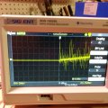
To measure ripple on the output of the buck regulator, you can use AC coupling with vertical sensitivity set appropriately (1V or less per division since you're seeing something on the order of 0.25V).
This is what I see. I don't know how to interpret it. (Or even if I've set the scope right. I've never taken the time to learn how to use it. I attached the leads to the + and - coming out of the buck controller.
I was using a filtering cap in the first pic. I tried it with values from.1uF ro 10uF. All the outputs look similar. Note that I changed the time to 25.0ms.
I was using a filtering cap in the first pic. I tried it with values from.1uF ro 10uF. All the outputs look similar. Note that I changed the time to 25.0ms.
From: Diode, Transistor & F ET Circuits Manual by R.M. MARSTON
As a rule of thumb, in a full-wave rectified power supply operating from a 50-60 Hz power line, an output load current of 100 mA will cause a ripple waveform of about 700 mV peak-to-peak to be developed on a 1000 μF filter capacitor, the amount of ripple being directly proportional to the load current and inversely proportional to the capacitance value, as shown in the design guide of Figure 1.18. In most practical applications, the ripple should be kept below 1.5 V peak-to-peak under full-load conditions.If very low ripple is needed, the basic power supply can be used to feed a three-terminal voltage regulator IС, which can easily reduce the ripple by a factor of 60 dB or so at low cost.
I haven't tried to do anything with it so far (other than try to measure the output) so I don't know. But the first thing I hoped to do with it was top balance $600 worth of LiFePO4 batteries so I don't want to experiment with those.
If very low ripple is needed, the basic power supply can be used to feed a three-terminal voltage regulator IС, which can easily reduce the ripple by a factor of 60 dB or so at low cost.
I've never seen a ceramic larger than 2.2uF. The filter caps are typically aluminum or tantalum electrolytics. Smaller value ceramics are used to filter higher frequency noise.
I have a proper BMS and a really good charger for regular charging when they are wired as 3.2V x 4 = 12.8V serial. and charging from solar panels. What my folks in the battery world (and the BMS manufacturer are suggesting is that I start by top balancing them wired as a 280aH parallel wired pack (3.2V). According to them, as long as I have a steady 3.6V to 3.65V and no more than .5C charging (10A would only be .1C), I can use any quality charger. I'm hoping I have a quality charger when this is all said and done....
I've never seen a ceramic larger than 2.2uF. The filter caps are typically aluminum or tantalum electrolytics. Smaller value ceramics are used to filter higher frequency noise.
I hesitate to say I got an assortment of ceramic 50V capacitors (.1uF to 10uF) from Aliexpress. So..... bigger is not always better. IF you can suggest a size and type cap, I will certainly buy it and try it.
I hesitate to say I got an assortment of ceramic 50V capacitors (.1uF to 10uF) from Aliexpress. So..... bigger is not always better. IF you can suggest a size and type cap, I will certainly buy it and try it.
I usually go for 470uF or 680uF electrolytics for supply filtering because I happen to have hundreds of them on hand.
I'm very cautious about buying components from Ali Express as there's too much counterfeiting in China. I buy assembled parts like Arduino Uno's and other assembled things, hardware (wire, jumpers, banana plugs/jacks, connectors), and tools without too much concern, but I have been burned more times than I'd prefer. Some stuff is junk, but I'm not out too much money when I find a particularly disreputable seller.
I haven't had any bad experiences yet. I also assumed most tiems sold in the US were imported from Asia anyway. But I suppose reputable companies (e.g. Mouser) have reputable sourcing unlike Aliexpress. Are things like transistors, capacitors, resistors and diodes usually counterfeited?
They counterfeit just about everything. Even surface mount ceramic capacitors that sell for less than half a cent. Chinese resistors tend to have skinny leads (and metallic magnetic from what I've read). Who knows what their temperature coefficients and tolerances are.
Some years back, a member bought some temperature sensors on eBay for a good price. It turned out they were actually transistors.
I buy most of my components from Jameco, Newark, Mouser, or Tayda Electronics. They only buy components from manufacturers or authorized resellers. Jameco and Newark have been including letters attesting authenticity in their shipments.
I used to buy components from eBay 10+ years ago, but no more unless it looks like someone selling an odd lot or company liquidation. I won't buy from Amazon either.
I bought some inexpensive surface mount P and N MOSFETs from AE. I ordered a hundred of each, did some spot testing and decided to buy a few hundred more. The parts were end of lifed and I thought about buying a reel (3000) of each. Then I saw pictures of a counterfeit market in China where they had reels of surface mount components and I chickened out. No way I was going to pay $30-40 for a reel and have them be counterfeit. The Chinese are sneaky about it. They'll include some good components, so you have to do 100% incoming QA. That is if you're able to. It's not worth the bother in my opinion.
 Facebook
 Google
 GitHub
 Linkedin