PSU Earthing issue?

Thread Starter

Paul_Alexa

Joined Jul 16, 2022
28
Hello, I am bothering you again with a question. I built a lab PSU using a cheap china kit and parts I had around. Whenever I switch it on I get 140-170 V AC between the psu's (-) terminal and mains earth. Not exactly pleasant to the touch since I have some screws holding in a display on the front.
I have sanded the paint off where the earth connects to the case. I have also checked for resistance between earth and various points of the psu's case.
To power the front panel electronics I am using an old phone charger. It is the two terminal type and it is well isolated. I have checked the PSU with it disconnected and I have observed no change.
Now, I know that this power supply is floating and that some voltage between earth and the (-) terminal is normal, but I don't believe it is normal to be this high.
The question that I have is: Have I done something wrong?
The transformer that I have used is an industrial one, made for powering 24V contactor coils. Maybe it is too leaky?
It is connected to earth through the bolts that secure it to the case. The connection is good.

Should I assume that my flat's earthing is horrible? I live in a former eastern bloc country in a flat built around the 70's.
I have experienced previous issues...
What should I do?
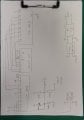
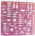
Thank you. Below I have attached a picture of the PSU.
 

Attachments

MaxHeadRoom

Joined Jul 18, 2013
30,557
Sounds like the integrity of your earth GND conductor is suspect.
How is it made or what is earth bonded to?
 
Last edited:

MisterBill2

Joined Jan 23, 2018
27,159
What I see in the photo is what looks like a link between the output red and black pair, and the mains blue and brown conductors, inside the black blob attached to the back side of the front panel. Also, with the disorganized wiring it is entirely possible that mains power has been connected to the DC output circuit at some point.
 

Thread Starter

Paul_Alexa

Joined Jul 16, 2022
28
Hello and thank you for the answer. The black blob is a 5volt switching PSU, a phone charger. I have checked the circuit without it and the issue persists.
 

Thread Starter

Paul_Alexa

Joined Jul 16, 2022
28
Sounds like the integrity of your earth GND conductor is suspect.
How is it made or what is earth bonded to?
I was wondering that as well. The flat building is old, built during the communist era.
The earthing is TN-C, I know that for sure.
Maybe somebody in the flat used an old iron heater as a ground?
Thank you for your time.
 

Pyrex

Joined Feb 16, 2022
501
Hi,
Take a 20 megohm 1W resistor and put it between PE and putput "-". It's better to use two resistors 10 megohm each in series for safety
 

Thread Starter

Paul_Alexa

Joined Jul 16, 2022
28
Hi,
Take a 20 megohm 1W resistor and put it between PE and putput "-". It's better to use two resistors 10 megohm each in series for safety
Hello and thank you for your answer.
I forgot to mention that I am using an ESP32 with an ADS1115 to measure some parameters of the psu (Current through a sensor, and voltage through a resistor divider)
The impedance of the ADS1115 is 6 M ohm and the electronics have common ground with the psu. Wouldn't that hurt the electronics?
 

Pyrex

Joined Feb 16, 2022
501
In most SMPS's you will get around 150V at the output, if mains is 230V . This is because of a slight current leakage.
If one's use a DMM with impedance of 10 megohms or so, a 100-150V will be detected. If a voltmeter with relatively low impedance is used, votage reading will be close to 0V.

Series Fiesta 016 True RMS AC Voltmeters - Analog Panel Meters - Analog & Digital Meters (spectrumind.com)

The high value resistor mentioned above is used to minimize the static buildup. This measure is useful, if output voltage exceeds 100VDC or above
 

MisterBill2

Joined Jan 23, 2018
27,159
OK, I went back and read the OP again. The voltage is between the supply negative and mains neutral, it appears. And verified. Now what are you touching that completes the circuit to deliver a shock?
Next question is do you have a circuit schematic for that power supply? examining that would tell us what to look at as a possible connection path to the mains.
In many appliance switching power supplies there is a well marked division between the isolated and non-isolated segments of the circuit. So if we can see the circuit that will be useful.
 

Thread Starter

Paul_Alexa

Joined Jul 16, 2022
28
In most SMPS's you will get around 150V at the output, if mains is 230V . This is because of a slight current leakage.
If one's use a DMM with impedance of 10 megohms or so, a 100-150V will be detected. If a voltmeter with relatively low impedance is used, votage reading will be close to 0V.

Series Fiesta 016 True RMS AC Voltmeters - Analog Panel Meters - Analog & Digital Meters (spectrumind.com)

The high value resistor mentioned above is used to minimize the static buildup. This measure is useful, if output voltage exceeds 100VDC or above
Thank you for the answer.
 

Thread Starter

Paul_Alexa

Joined Jul 16, 2022
28
OK, I went back and read the OP again. The voltage is between the supply negative and mains neutral, it appears. And verified. Now what are you touching that completes the circuit to deliver a shock?
Next question is do you have a circuit schematic for that power supply? examining that would tell us what to look at as a possible connection path to the mains.
In many appliance switching power supplies there is a well marked division between the isolated and non-isolated segments of the circuit. So if we can see the circuit that will be useful.
I touched some screws that hold a display on the front panel that deliver the shock. Nothing else.
I have attached a photo of the pcb layout, the psu's schematich and the front panel that I have built. During switching on and off the psu ocasionally delivered some transients and I added an overvoltage/reverse voltage protection on the A0 pin. Sorry for the hand drawn schematic.
Thank you for your time.
 

Attachments

MisterBill2

Joined Jan 23, 2018
27,159
OK, and thank you for having the schematic available.. Now the reason for the voltage is very clear and obvious: This is not an isolated power supply!
The circuit negative connection, between D3 and D4, is connected directly to the negative output, (terminal #4) through resistor R7, which appears to be a 4.7K (4700 ohms) resistor. So certainly there is an actual connection.
That also means that if you are able to connect the supply negative to the mains neutral the circuit will not function correctly and it may be damaged.
Others are welcome to examine the supplied schematic and verify this opinion. So my suggestion is to get an isolation transformer so that the input connections, terminals #1 and #2, are isolated from the mains supply.
But now it seems that there already is an isolation transformer present, and that it is already connected to the circuit board. if that is the case, then the high voltage is arriving from another source.
So you meed to do a resistance check with the whole power supply assembly disconnected from the mains. Check the resistance between the mains connector and the power supply terminals. AND check for any continuity between the transformer primary terminals and the secondary terminals. It should be an open circuit.
 

KeithWalker

Joined Jul 10, 2017
3,603
I touched some screws that hold a display on the front panel that deliver the shock. Nothing else.
I have attached a photo of the pcb layout, the psu's schematich and the front panel that I have built. During switching on and off the psu ocasionally delivered some transients and I added an overvoltage/reverse voltage protection on the A0 pin. Sorry for the hand drawn schematic.
Thank you for your time.
It is quite normal to measure an AC voltage between an isolated circuit common and earth ground or neutral using a high impedance voltmeter. The voltage is caused by capacitive coupling between the primary and secondary windings on the transformer. If the end of the primary winding closest to the secondary is connected to the live terminal of the supply, the voltage can be quite high. Try reversing the mains connections to the transformer. It will probably reduce the measured voltage. Some high quality power transformers have a grounded electrostatic shield between the primary and secondary windings to reduce the capacitive coupling.
The best way to minimise this problem is by disconnecting the metal case of the supply from the circuit common and connecting it to the supply ground. This is the way commercial lab supplies are usually wired, with a ground terminal connected to the case, close to the output terminals.
 
Last edited:

seanstevens

Joined Sep 22, 2009
323
OK, and thank you for having the schematic available.. Now the reason for the voltage is very clear and obvious: This is not an isolated power supply!
To me, it looks like points 1 & 2 are where the secondary of the AC step-down transformer connects to. with most of the R/C/D connected to the bridge generating a negative supply for the opamps. So, I don't think this is a non-isolated PSU. Most likely there is an issue somewhere in the wiring.
 

KeithWalker

Joined Jul 10, 2017
3,603
OK, and thank you for having the schematic available.. Now the reason for the voltage is very clear and obvious: This is not an isolated power supply!
The circuit negative connection, between D3 and D4, is connected directly to the negative output, (terminal #4) through resistor R7, which appears to be a 4.7K (4700 ohms) resistor. So certainly there is an actual connection.
That also means that if you are able to connect the supply negative to the mains neutral the circuit will not function correctly and it may be damaged.
Others are welcome to examine the supplied schematic and verify this opinion. So my suggestion is to get an isolation transformer so that the input connections, terminals #1 and #2, are isolated from the mains supply.
But now it seems that there already is an isolation transformer present, and that it is already connected to the circuit board. if that is the case, then the high voltage is arriving from another source.
So you meed to do a resistance check with the whole power supply assembly disconnected from the mains. Check the resistance between the mains connector and the power supply terminals. AND check for any continuity between the transformer primary terminals and the secondary terminals. It should be an open circuit.
To me, it looks like points 1 & 2 are where the secondary of the AC step-down transformer connects to. with most of the R/C/D connected to the bridge generating a negative supply for the opamps. So, I don't think this is a non-isolated PSU. Most likely there is an issue somewhere in the wiring.
He is using an industrial 24V isolation transformer and there is no ground connection shown in the circuit diagram, so this power supply is isolate from ground!.
 

Pyrex

Joined Feb 16, 2022
501
It seems to me, the transformer 230/24V 50VA can't be so leaky to cause a shock. What else- a small SMPS in black wrapping. It was said, the problem persist even it's was disconnected.

I see the only solution- to perform a hipot ( dielectric withstand ) test. Test voltage -500 or 1000VDC. Simply borrow a megger and check the resistance.

It's for your own safety !
 

KeithWalker

Joined Jul 10, 2017
3,603
It seems to me, the transformer 230/24V 50VA can't be so leaky to cause a shock. What else- a small SMPS in black wrapping. It was said, the problem persist even it's was disconnected.
The power supply is isolated from ground so it will also build up a static charge which CAN give a mild shock!
I still suggest that he connects the power supply as I described above. The commercially available lab power supplies are connected this way to prevent shocks and to protect devices connected to the power supply.
 

Thread Starter

Paul_Alexa

Joined Jul 16, 2022
28
OK, and thank you for having the schematic available.. Now the reason for the voltage is very clear and obvious: This is not an isolated power supply!
The circuit negative connection, between D3 and D4, is connected directly to the negative output, (terminal #4) through resistor R7, which appears to be a 4.7K (4700 ohms) resistor. So certainly there is an actual connection.
That also means that if you are able to connect the supply negative to the mains neutral the circuit will not function correctly and it may be damaged.
Others are welcome to examine the supplied schematic and verify this opinion. So my suggestion is to get an isolation transformer so that the input connections, terminals #1 and #2, are isolated from the mains supply.
But now it seems that there already is an isolation transformer present, and that it is already connected to the circuit board. if that is the case, then the high voltage is arriving from another source.
So you meed to do a resistance check with the whole power supply assembly disconnected from the mains. Check the resistance between the mains connector and the power supply terminals. AND check for any continuity between the transformer primary terminals and the secondary terminals. It should be an open circuit.
Thank you for your answer. I have performed the checks. I get an open circuit between the power supply's (-) or (+) and any combination of the mains connector. Testing the transformer primary to secondary continuity also revealed an open circuit.
 
Top