 Facebook
 Google
 GitHub
 Linkedin
Hi,
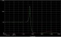
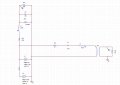
I work with PSpice 16.3. for my school project. I have to simulate PLC (power line communication) device. I want to extract high frequency signal, from power line network using band pass filter. So I have created band pass filter. Put two sources (one with 50Hz and the second one with 100kHz) and also I have try to simulate the rest of the power line (parametres are count for 3 km from avarage values for power line 22kV). But there is a problem. I think PSpice doesn´t see it all like one object. And that I have created something like weird low pass filter. And I can´t replace it just by resistor, because it's not correct.
Do you have any advice, how can I simulate power line, or if PSpice contain something like impedance Z?? Or did I just make some stupid mistake??
I will be grateful for any advice and if I forget write some information about my circuit, I will add it as soon as possible.
Thanks.
Attachments
-
 77.4 KB Views: 79
 -
 68.2 KB Views: 80
 -
 135.9 KB Views: 58


