Prototype to PCB advice

Thread Starter

loveforcircuits

Joined Jan 31, 2026
157
For a removable expansion module, would you recommend a edgeboard connector or a mezzanine board-to-board connector? I'm interested in durability and assembly cost. I came across these edgeboard connectors Are there drawbacks I should know about?

I want to design a PCB for a clock using Arduino Mega, DS1307 RTC module and 1.54” e-ink display module(monochrome). The main board will contain the Arduino Mega, DS13007 RTC module and battery. A small front-panel board will hold the E-ink display. My current prototype does not have any push button but I need to add some of course. I'd like the front-panel board to be removable.

Here is a picture of my current prototype.
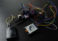
Screenshot 2026-08-19 181828.png
 

panic mode

Joined Oct 10, 2011
5,189
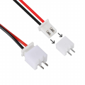
i would consider making buttons separate, for that i would use 2-pin JST connector - small and cheap.
board can have few buttons and resistors, forming multi-level voltage divider, that is easily read by ADC.
1787145477440.png
for display i would run cable directly to Arduino. or... put everything on a single shield.
 
Last edited:
For added functionality, mezzanine board-to-board makes more sense BECAUSE it is more compact and takes up less space and it provides greater flexibility. It might also cost less than an edge connector plus the plated PCB fingers. IN ADDITION, most mezanine connectors are cheaper and much more reliable than consumer grade edge connectors.
 

dl324

Joined Mar 30, 2015
18,449
For a removable expansion module, would you recommend a edgeboard connector or a mezzanine board-to-board connector? I'm interested in durability and assembly cost. I came across these edgeboard connectors Are there drawbacks I should know about?
Why would you consider card edge connectors when virtually nothing uses them these days? Because most boards have either male or female 0.025" square headers, using them makes more sense.
 
For this application I would avoid a card-edge connector. It requires wear-resistant gold fingers and potentially a bevel, adding fabrication requirements that bring little benefit for a small number of display and button signals. PCBWay’s edge-connector guide illustrates the additional gold-finger and chamfer specifications involved.

A mezzanine connector works well only if the boards are rigidly mounted, parallel and accurately aligned with standoffs. If the front panel and main board may move independently, a short FFC or locking wire-to-board cable would tolerate mechanical and assembly variation better. It would also make removing the front panel easier.

For an initial prototype, ordinary 0.1-inch headers are inexpensive and easy to debug. Once the enclosure dimensions are fixed, replace them with a keyed mezzanine or FFC connector having enough contacts for:

  • Display power and ground
  • SPI and display-control signals
  • Button signals
  • One or two spare pins

Also verify the voltage levels before laying out the boards. The Arduino Mega and DS1307 commonly operate at 5 V, whereas many e-paper displays use 3.3 V logic. Some display modules include level shifting, but this should be confirmed rather than assumed.
 

MisterBill2

Joined Jan 23, 2018
28,070
I have seen working assemblies of mezanine style PCBs that look a lot like they have used those "wire wrap" sockets for interconnects between levels. Certainly it takes some focussed attention to align the posts with the sockets, but they do go together well and it is a rather cheap way to go, at least for hobby-class projects.
 
Top