proportional valve control circuit help

Thread Starter

woerr

Joined Apr 5, 2015
40
Good day

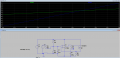
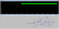
I am looking for some ideas to convert a 12v pwm signal to 6-9v analogue signal.

I need to drive a hydraulic proportional valve, where neutral is 0.5*udc and control range is 0.5*udc(6v) to 0.75*udc(9v).

The current draw of the control signal is 10W.

Doing a simple low pass filter will give me 0-12v which will only work if i limit my pwm signal to from 50% - 75% which will severely limit the precision i need(I assume). also the valve doesn't work with pwm directly. So I assume the only way to get it to work is to use a variable voltage regulator which limits can be adjusted using resistors and voltage can be adjusted using pwm, but this is where my expertise ends..

Edit: I forgot to add that pwm frequency is 490Hz.
 
Last edited:

Alec_t

Joined Sep 17, 2013
14,280
Here's the basis for one option:
PWM-to-ControlV.PNG
C1 integrates the PWM signal, assumed to be of a frequency around 1kHz. The resistor combination R1,2,3 yields a 6V-9V voltage for controlling the opamp, which drives a P-MOSFET to give a 6V-9V voltage across the load. R4 and C2 suppress oscillation.
 

Thread Starter

woerr

Joined Apr 5, 2015
40
Here's the basis for one option:
View attachment 139836
C1 integrates the PWM signal, assumed to be of a frequency around 1kHz. The resistor combination R1,2,3 yields a 6V-9V voltage for controlling the opamp, which drives a P-MOSFET to give a 6V-9V voltage across the load. R4 and C2 suppress oscillation.
I dont understand how driving the gate of the FET linearly changes the voltage. I thought the are only on or off.

Edit: did some research and found this:
"the MOSFET will be in a partially conducting state. They are sometimes used this way in linear-type amplifiers. However, they dissipate a lot of power when used this way."

From this I gather that I do not want a logic level pfet for this application.
 
Last edited:

Alec_t

Joined Sep 17, 2013
14,280
I thought the are only on or off.
They are commonly used as on/off switches and for that purpose they dissipate little power.
When used in the partially-conducting state, as here, they do dissipate considerable power.
You mentioned 10W. Is that the figure or did you mean 10A? Whatever, the FET will need a suitably-rated heatsink.
A logic-level P-FET shouldn't be necessary (but won't hurt) if the output of the chosen opamp can get within a volt or two of the ground rail (most can).
 

MaxHeadRoom

Joined Jul 18, 2013
28,619
I once did a proportional valve application using a Nat. LM759, the app note shows a DC servo motor example, just one power op-amp.
Modern replacements are OPA547 L165 etc.
Max.
 
Last edited:

Thread Starter

woerr

Joined Apr 5, 2015
40
I recreated your circuit to better understand it in ltspice, I got the same linear voltage output as you, but changing it to PWM at 490Hz and 50% duty cycle, im worried some issues may come from the sawtooth pattern.


Attachments

Kjeldgaard

Joined Apr 7, 2016
476
I recreated your circuit to better understand it in ltspice, I got the same linear voltage output as you, but changing it to PWM at 490Hz and 50% duty cycle, im worried some issues may come from the sawtooth pattern.
Try make a new simulation with an extra pole in the filter.

Components for the same time constant can be 15K and 1uF.
 

Thread Starter

woerr

Joined Apr 5, 2015
40
It looks much better, but I dont understand whats happening at 150ms here.

Edit: its either oscilation due to bad resistor and cap values or a bug in the program.


Attachments

Last edited:

Kjeldgaard

Joined Apr 7, 2016
476
It looks much better, but I dont understand whats happening at 150ms here.

Edit: its either oscilation due to bad resistor and cap values or a bug in the program.
I meant a passive extra R/C pole to ground, in the connection between the top of the C1 and the inverting input of the amplifier.
 

Alec_t

Joined Sep 17, 2013
14,280
I dont understand whats happening at 150ms here.
It's oscillation as a result of delay in the opamp and FET gate capacitance charging/discharging. That's why I included R4 and C2. I note you reduced C2 to 1uF?
Here's the sim with the added RC suggested by Kjeldgaard.
Although the ripple in the opamp inverting input is now negligible, there is still some jitter in the voltage across the load. I don't think this will be a problem for the proportional valve: it may even be an advantage. I understand it is common to introduce a dither voltage to help overcome valve stiction.
 

Attachments

Last edited:

Thread Starter

woerr

Joined Apr 5, 2015
40
cir4.png

Thant looks really good, going to order parts to start testing.

Tyvm

EDIT: you cant really see the blue line here, but its perfectly stable.
EDIT: I removed R4 and C2, no change.
 
Last edited:

Alec_t

Joined Sep 17, 2013
14,280
Looks like the limited current available from the opamp is a factor that also contributes to the dither in the load voltage. Here's another option to reduce the dither, if you feel that's necessary. Q1 and Q2 provide a boosted gate charge/discharge current.
PWM-to-ControlV3.PNG
Note that the load here is an inductor, modelling the valve coil.
 

strantor

Joined Oct 3, 2010
6,782
What proportional valve is this? The control voltage specs sound like Danfoss PVG. If that's the case, the control voltage does not need any current. The amplifier is built into the valve.
 

Thread Starter

woerr

Joined Apr 5, 2015
40
There is a built in amplifier and control circuit, but the current required according to the spec sheet is 10W. the device im using is a youli PVEM.
 

strantor

Joined Oct 3, 2010
6,782
Yes that's a shameless clone of Danfoss PVG series, PVE proportional controller. Even the datasheet is nearly a copy of Danfoss' datasheet LOL. I'm curious how much this cost compared to the original Danfoss part.

Any way, it is as I suspected. The unit requires 12V or 24V power, and a separate voltage signal. Your voltage signal does not need to proved any 10W of power. You can actually control this unit with a potentiometer.
 
Top