Proper Usage of LM317 for Voltage Divider?

Thread Starter

Robert Brienza

Joined Jun 10, 2015
7
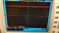
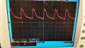
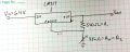
I'm trying to construct a 3.3 V power supply using an old laptop charger as an input voltage of 6.4 V. I am using an LM317 regulator and two external resistors to provide an output voltage of 3.3V. R1 is fixed while R2 is a 10k pot that can be finely adjusted to within an ohm or so. When no load is connected, I get my output to be what I want, and I can adjust the potentiometer to adjust my voltage. I used the formula Vout = 1.25 V * (1 + R2/R1), which is in the LM317 datasheet. However, I've come to realize that when low resistance loads are connected to the output, my output voltage drops considerably. I tested a 14 Ohm resistor by connecting it between the output and ground, and the voltage across it ended up being 0.27 V. This does not happen with large resistances.

I've looked through some old posts and I found that the resistance for R1 is highly recommended to be 120 Ohms. However, I found a website (link below) that essentially says anywhere from 100 to 1000 Ohms is fine, and because I was getting my desired voltages without a load connected, it seemed that this shouldn't be an issue. However, I have little experience with this circuit element so I'm not sure.

http://www.reuk.co.uk/LM317-Voltage-Calculator.htm


I understand that the output of a simple voltage divider without a regulator can be affected by small loads, which is why I included the regulator in the first place. Ultimately I would like to use this to power an AD9914 DDS, but for now I have been testing it on resistors. Included below is my circuit and the datasheet for the LM317. I see also that in the LM317 datasheet, two capacitors are inserted to provide some sort of stability. How necessary are these, and could leaving these out be the cause of my problem? I'd like to understand the theory behind how a regulator circuit works instead of blindly copying a circuit and using an equation that I don't understand. If it helps, I have previous experience using op-amps in a lab. Thanks in advance.
 

Attachments

MikeML

Joined Oct 2, 2009
5,444
Cut the 540Ω to 240Ω or less, and recalculate the other resistor. The data sheet is very specific about this restriction because of the minimum load current spec. REUK is full of crap!

If you run without the capacitors, the regulator can oscillate, and voltages measured with an DMM will be all over place. It would take an oscilloscope to "see" the oscillation.
 

ErnieM

Joined Apr 24, 2011
8,415
Here's how this little thing works to regulate the voltage out: what it does internally is regulate the voltage between the OUT and ADJUST pins. That voltage is nominally 1.25 V, and is in that spec sheet on sheet 2 as "Reference Voltage".

When you put the 540 ohm resistor there for R1 you cause a current of 1.25/540=2.3mA to flow thru thru R2. 886 ohms x 23mA = 2.0V, and add back in the 1.25V across R1 and you see the voltage across both R1 and R2 is 3.3V.

Now some current does flow out of the ADJUST pin (look right above "Reference Voltage" on the spec sheet) which throws the value off some, but this should raise the net output voltage from the calculation. Keeping R1 to the recommended 240 ohms makes this current very small compared to the current you are using to set the voltage.

A 14 ohm load on 3.3V is .23 amps which should be OK. If you only see .27 volts there that means you are only drawing 19 mA from this thing. That sounds wrong, I would recheck and check again your wiring and if the 14 ohms is really 14 ohms. Also check if the input voltage is still what you think it is.

And welcome to the forums!
 

AnalogKid

Joined Aug 1, 2013
12,174
Check the pinout and your connections, and remember that the tab is electrically connected to the circuit. If the part is on a heatsink, it should be insulated.

ak
 

Thread Starter

Robert Brienza

Joined Jun 10, 2015
7
I rebuilt the circuit with R1 = 197 Ohm and R2 = 323 Ohm. The problem persists, unfortunately. I've rebuilt the circuit several times over the last few days, so it seems unlikely that this is due to improper wiring, although it's still possible.

Check the pinout and your connections, and remember that the tab is electrically connected to the circuit. If the part is on a heatsink, it should be insulated.

ak
My regulator is on a heatsink, but could you explain more what you mean when you say the tab is electrically connected? I'll attach a photo of my current setup. I don't see why any insulation should be necessary.

Here's how this little thing works to regulate the voltage out: what it does internally is regulate the voltage between the OUT and ADJUST pins. That voltage is nominally 1.25 V, and is in that spec sheet on sheet 2 as "Reference Voltage".

When you put the 540 ohm resistor there for R1 you cause a current of 1.25/540=2.3mA to flow thru thru R2. 886 ohms x 23mA = 2.0V, and add back in the 1.25V across R1 and you see the voltage across both R1 and R2 is 3.3V.

Now some current does flow out of the ADJUST pin (look right above "Reference Voltage" on the spec sheet) which throws the value off some, but this should raise the net output voltage from the calculation. Keeping R1 to the recommended 240 ohms makes this current very small compared to the current you are using to set the voltage.

A 14 ohm load on 3.3V is .23 amps which should be OK. If you only see .27 volts there that means you are only drawing 19 mA from this thing. That sounds wrong, I would recheck and check again your wiring and if the 14 ohms is really 14 ohms. Also check if the input voltage is still what you think it is.

And welcome to the forums!
Thank you for the explanation, that helps a lot. I rechecked the resistor and voltage, and I am getting 0.27 V still, while the resistor is anywhere between 11.6 and 14 Ohm, depending on what wires I use to connect it to my multimeter. I just measured my input voltage at 6.4 V, and my output without a load is 3.32 V currently.
 

Attachments

Lestraveled

Joined May 19, 2014
1,946
You need a decoupling capacitor(s). Look at the first page of the spec sheet. At minimum, You need a .1uF from the input pin to ground. A 10 uF from the output pin to ground is a very good thing to add. As MikeML stated, without caps it will probably oscillate.
 

AnalogKid

Joined Aug 1, 2013
12,174
The metal tab on a TO-220 package actually is pin 4 of the device. Sometimes it is insulated, but most of the time it is connected internally to the center pin as shown above. So whatever voltage is on pin 2 also is on the tab. This means that you must pay attention to whatever is touching the device, heatsink, mounting screw, etc.

Where did you get a 540 ohm resistor? That is not a standard value. Also, I recommend changing it to 120 ohms and redoing R2 to match. "R1 is highly recommended to be 120 Ohms" for a reason. Rather than deviate from the manufacturer's direction and then ask why it doesn't work, start with exactly what is recommended, get that to work, and only then start changing things. The datasheet app notes are not the only things that will work, but if you are not already familiar with the part they are the only place to start.

ak
 

Thread Starter

Robert Brienza

Joined Jun 10, 2015
7
The metal tab on a TO-220 package actually is pin 4 of the device. Sometimes it is insulated, but most of the time it is connected internally to the center pin as shown above. So whatever voltage is on pin 2 also is on the tab. This means that you must pay attention to whatever is touching the device, heatsink, mounting screw, etc.

Where did you get a 540 ohm resistor? That is not a standard value. Also, I recommend changing it to 120 ohms and redoing R2 to match. "R1 is highly recommended to be 120 Ohms" for a reason. Rather than deviate from the manufacturer's direction and then ask why it doesn't work, start with exactly what is recommended, get that to work, and only then start changing things. The datasheet app notes are not the only things that will work, but if you are not already familiar with the part they are the only place to start.

ak
I understand now. I am sure that my heatsink, mounting screw, and pin 4 are all insulated from any grounds or voltages.

My lab had a 540 Ohm resistor on hand (I measured this using an ohmmeter, I don't remember what the color code was), and the link I originally posted said 100-1000 was okay, which is why I used it. The consensus here is that the link is wrong, which is why I have since changed R1 to 197 Ohm, which is another resistor we had on hand. I don't understand why everyone here recommends 120 Ohm while the datasheet recommends 240, but is it reasonable to assume that 197 should also work? If not, how close do I need to get? I also built a separate 1.8 V supply using a 159 Ohm resistor and a 70 Ohm resistor, which obviously is encountering the same problems.

When no load is connected, the oscilloscope gives a totally DC reading, but when a load is connected it starts to oscillate strangely, and perhaps my voltmeter is simply giving me an RMS value of that oscillation, instead of constantly changing, which is why the voltage appears to drop. I will rebuild the circuit with the decoupling capacitors. I appreciate all the input I have gotten so far. I know it can be frustrating to explain this to someone who has barely any idea of how this stuff works. Thank you for your patience.
 

dl324

Joined Mar 30, 2015
18,403
I don't understand why everyone here recommends 120 Ohm while the datasheet recommends 240, but is it reasonable to assume that 197 should also work? If not, how close do I need to get? I also built a separate 1.8 V supply using a 159 Ohm resistor and a 70 Ohm resistor, which obviously is encountering the same problems.
LM317 have a minimum load current of 10mA (max), though it's typical value is 3.5mA - from a Nat Semi datasheet. If you use a 120 ohm resistor to set the adjust current, the maximum minimum load current is satisfied. If you use a larger resistor, you need to make sure that the total load current satisfies the minimum load; using 10mA means you don't have to worry whether or not your part typical.

I typically use a 274 ohm resistor to set the adjust current and in several decades of using LM317, I've only had one that required an additional load to work. I had a load on it, but it was too small and I had to add a resistor to increase the load...

EDIT: BTW, nominal resistor value is usually given; not measured value. People who have knowledge of standard resistor values would have no problem identifying the 274 ohm resistor mentioned above as 1% tolerance.
 
Last edited:

ronv

Joined Nov 12, 2008
3,770
I understand now. I am sure that my heatsink, mounting screw, and pin 4 are all insulated from any grounds or voltages.

My lab had a 540 Ohm resistor on hand (I measured this using an ohmmeter, I don't remember what the color code was), and the link I originally posted said 100-1000 was okay, which is why I used it. The consensus here is that the link is wrong, which is why I have since changed R1 to 197 Ohm, which is another resistor we had on hand. I don't understand why everyone here recommends 120 Ohm while the datasheet recommends 240, but is it reasonable to assume that 197 should also work? If not, how close do I need to get? I also built a separate 1.8 V supply using a 159 Ohm resistor and a 70 Ohm resistor, which obviously is encountering the same problems.

When no load is connected, the oscilloscope gives a totally DC reading, but when a load is connected it starts to oscillate strangely, and perhaps my voltmeter is simply giving me an RMS value of that oscillation, instead of constantly changing, which is why the voltage appears to drop. I will rebuild the circuit with the decoupling capacitors. I appreciate all the input I have gotten so far. I know it can be frustrating to explain this to someone who has barely any idea of how this stuff works. Thank you for your patience.
Did you add the capacitors shown on the first page of the data sheet?
 

Thread Starter

Robert Brienza

Joined Jun 10, 2015
7
I added a 1.5 microfarad capacitor between the input voltage and ground as in the datasheet, but I didn't notice any difference in the signal. On an oscilloscope it still oscillates at a frequency of 7 Hz in an asymmetrical pattern. I'll take a picture tomorrow to show what I mean. Afterwards I added a 47 microfarad capacitor between the output and ground, which didn't change the output. Again, I know I'm not using the recommended value in the datasheet. It was honestly the closest value that we have in the lab, and the electronics shop we usually have access to has been closed the last few days. By Lestraveled's earlier comment it seems the higher the better, though.

LM317 have a minimum load current of 10mA (max), though it's typical value is 3.5mA - from a Nat Semi datasheet. If you use a 120 ohm resistor to set the adjust current, the maximum minimum load current is satisfied. If you use a larger resistor, you need to make sure that the total load current satisfies the minimum load; using 10mA means you don't have to worry whether or not your part typical.

I typically use a 274 ohm resistor to set the adjust current and in several decades of using LM317, I've only had one that required an additional load to work. I had a load on it, but it was too small and I had to add a resistor to increase the load...

EDIT: BTW, nominal resistor value is usually given; not measured value. People who have knowledge of standard resistor values would have no problem identifying the 274 ohm resistor mentioned above as 1% tolerance.
I'm pretty sure I get what you're saying, but "maximum minimum load current" is a bit confusing. Thanks for the input.
 

dl324

Joined Mar 30, 2015
18,403
On an oscilloscope it still oscillates at a frequency of 7 Hz in an asymmetrical pattern.
Since you have a scope, what does the input to the regulator look like?
Afterwards I added a 47 microfarad capacitor between the output and ground, which didn't change the output.
More isn't necessarily better...
Again, I know I'm not using the recommended value in the datasheet.
They're just guidelines. An output capacitor isn't always required. The 0.1uF ceramic on the input depends on how the input voltage is generated.
I'm pretty sure I get what you're saying, but "maximum minimum load current" is a bit confusing.
Perhaps a comma would have made it less confusing. The minimum load current has a maximum value of 10mA; typical value is 3.5mA.
 

dl324

Joined Mar 30, 2015
18,403
Please decrease the size of your photos. The upload widget used to ask you to limit size to a few hundred KB...

What are the specs on the 6.4V charger you're using and what type of load are you driving?
 

Thread Starter

Robert Brienza

Joined Jun 10, 2015
7
Here's a reduced-size picture of the charger. The previous oscilloscope screen with the dramatic oscillation had my 1.8V output connected to an AD9914 evaluation. At this point my entire circuit is fairly similar to the one in the datasheet. The only changes are:

1. I split the input voltage towards two separate LM317s each with their own resistors and output capacitors, so that I produce 3.3V and 1.8V
2. My input capacitor is 0.15 instead of 0.1 microfarad ( I think I made a typo earlier), and my output capacitors are 47 instead of 1 microfarad.

The same "strange" oscillation when connected to the AD9914 also occurred when connected to a small load, like the 14 ohm resistor.​
 

Attachments

dl324

Joined Mar 30, 2015
18,403
In your original post, you said the "laptop charger as an input voltage of 6.4 V". Which I took to mean that it's output voltage was 6.4V. Are you using the 5V output?
 

Thread Starter

Robert Brienza

Joined Jun 10, 2015
7
In your original post, you said the "laptop charger as an input voltage of 6.4 V". Which I took to mean that it's output voltage was 6.4V. Are you using the 5V output?
I inspected the cable more closely, and saw that it contained 2 wires but also some braided copper wire. Unfortunately I have been careless. Because I inherited this project from another student, I assumed that the white wire was ground while the red was 6.4 V, but I was mistaken. The braided copper wire was ground, while the white was 5 V.

I am now using the 12 V output and the proper ground. The circuit now deliver my desired 3.3 V and 1.8 V when connected to the evaluation board. Thank you everybody for all of your help. It really does take a group effort to catch mistakes like the one I made.
 
Top