Proper direction of a P-Channel Mosfet

Thread Starter

jerseyguy1996

Joined Feb 2, 2008
214
In figure 2 of this app note:

http://ww1.microchip.com/downloads/en/AppNotes/01149c.pdf

I feel like Q1 is facing the wrong direction. Doesn't the pin with the little arrow attached to it supposed to be on the +V side and the other pin supposed to be on the load side? Also, isn't the internal diode supposed to be facing the other direction? I duplicated this circuit with a slightly different charge management controller but now I am starting to have a funny feeling that it may be wrong.
 

LDC3

Joined Apr 27, 2013
924
I think the diagram is correct. If the only power is from the battery, the MOSFET is turned on. If the external voltage is greater than the battery, the battery is disengaged from the load.
For information on p-channel MOSFETs, go here.
 

crutschow

Joined Mar 14, 2008
38,938
A MOSFET will conduct in either direction when Vgs is above the threshold voltage. They are thus sometimes used to conduct in the reverse direction to avoid forward biasing the body diode when the voltage becomes reversed (which now forward biases the MOSFET).
 

Thread Starter

jerseyguy1996

Joined Feb 2, 2008
214
I think where I am confused is that in this image:


the drain is connected to the load whereas in Figure 2 of my previously linked appnote it appears that the source is connected to the load. What am I getting wrong here?
 

Thread Starter

jerseyguy1996

Joined Feb 2, 2008
214
Oops....didn't see your reply there. I did not know that a mosfet conducts in both directions when the appropriate voltage is applied to the gate. You just blew my mind a bit :) Is the behavior of the mosfet different such as the voltage drop and RDSon depending on the direction of current?
 

Thread Starter

jerseyguy1996

Joined Feb 2, 2008
214
Also I'm trying to think this through and it is kind of making my brain hurt a bit, but since the gate voltage is referenced to the source, it seems to me that in that configuration, if there was a sudden current demand by the load, it could pull the source voltage down to a point where the gate to source voltage drops into the linear region which would exacerbate the problem and it would eventually reach a point where the gate to source voltage would drop below the threshold voltage. Is this a concern? I could be completely backwards on this though.
 

Jony130

Joined Feb 17, 2009
5,601
Almost all discrete MOSFET has build-in parasitic diode (body diode with cathode on the source, anode on the drain for P-channel). This diode will not conduct until drain voltage will be greater then the source voltage. If Vds > 0.6V body diode is OFF.
So until the diode is OFF you can swap the drain and source.
 

crutschow

Joined Mar 14, 2008
38,938
A MOSFET's channel is bidirectional so it will conduct equally well in both directions as long as the Vgs turn-on voltage is maintained. From a physics point of view either end of the MOSFET can act as the source, it just depends upon the relative voltages. The reason they are normally only connected one way is to avoid conduction in the substrate diode which has the anode connected to the drain and the cathode connected to the source in a P-MOSFET. As long as you don't forward bias that diode the MOSFET works in both directions.

This is useful if you want to isolate a source from a load when the load can be supplied by more than one source. For a plus supply voltage you would then use a P-MOSFET with the source towards the load. Grounding the gate will turn on the MOSFET. Connecting the gate to the source will turn off the MOSFET and isolate any load voltage from the source.

If the voltage drops due to excessive load then, yes the transistor may start to turn off, at least until the drain-source diode starts to conduct.
 

tracecom

Joined Apr 16, 2010
3,944
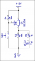
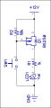
Ironic! I just went through this yesterday, creating a new P-channel component for my DipTrace library, and using it in a schematic. After what I have read here, I'm no longer sure I got it right. The LED lights when the switch is closed.

What say?
 

Attachments

Thread Starter

jerseyguy1996

Joined Feb 2, 2008
214
Ironic! I just went through this yesterday, creating a new P-channel component for my DipTrace library, and using it in a schematic. After what I have read here, I'm no longer sure I got it right. The LED lights when the switch is closed.

What say?
The LED should light when the switch is closed because you are grounding the gate relative to the source voltage. What's the point of R3 though?
 

tracecom

Joined Apr 16, 2010
3,944
Yes, you don't need this resistor in this application.
I actually extracted that from a larger circuit, and didn't think much about R3. Thanks.

What about the P-channel MOSFET symbol itself; is it OK? And is placing the drain at the bottom of the schematic correct?
 

tracecom

Joined Apr 16, 2010
3,944
That looks fine, but couldn't you just do without the mosfet all together and just run the 12V through the switch to the Resistor and LED?
Sure. I just was documenting (for my own records) a correct way to use a P-channel MOSFET as a high side switch. I actually built a circuit yesterday that used this configuration and the LED was there simply as a visual indication that the MOSFET was on.
 

Thread Starter

jerseyguy1996

Joined Feb 2, 2008
214
Sure. I just was documenting (for my own records) a correct way to use a P-channel MOSFET as a high side switch. I actually built a circuit yesterday that used this configuration and the LED was there simply as a visual indication that the MOSFET was on.
I do that kind of stuff all of the time. Sort of proving to myself that it does actually work:)
 

crutschow

Joined Mar 14, 2008
38,938
...............

What about the P-channel MOSFET symbol itself; is it OK? And is placing the drain at the bottom of the schematic correct?
Yes. If you connected it backwards, the LED would be on all the time because of conduction through the substrate diode.
 
Top