Facebook
 Google
 GitHub
 Linkedin
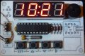
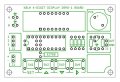
I'd like to share a relatively simple "single chip" 4-digit LED Clock project that uses a PIC16F1828 microcontroller, a 32768 Hz crystal time base, a four digit LED display, and just a handful of other parts. This low parts count design is due in part to experiments with some very bright miniature multiplexed 4-digit displays which are available from Sparkfun in red, green, yellow, white (all $1.95), and blue ($2.50) colors.

Hardware
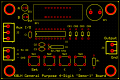
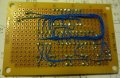
The circuit was built on a Radio Shack prototype board (sku 276-149) with a plastic laminated paper silk-screen glued onto the component side of the board. I used 30 guage Kynar wire and point-to-point wiring on the copper side of the board.
The circuit does not include column/digit driver transistors and relies on the combined ~250 ohm RDS(ON) resistance of the PIC I/O pin high side and low side FET drivers for segment current limiting. The display is refreshed one segment at a time (1/32nd duty cycle) to provide even brightness across the entire display.

Parts List
Software
The HEX file in the ZIP file attachment can be used directly with a PICKIT2, PICKIT3, or similar device programmer to program the PIC16F1828. The program source file is also included in the ZIP file attachment. The program was written using the free/lite version of BoostC from Sourceboost and it uses 339 of the 4096 words of program memory available in the 16F1828.
The program configures the 16F1828 to run from the internal oscillator at 8-MHz and the Timer 2 module is configured to generate 250-usec (500 cycle) periodic interrupts. The Timer 1 low power oscillator is enabled for the 32768 Hz crystal. The ISR (interrupt service routine) is responsible for refreshing one new segment of the display each interrupt and it also polls Timer 1 for one second time-base intervals for the RTC. All thirty two segments of the display are updated once every 8-msecs for a 125-Hz refresh rate (1/32nd duty cycle).
Operation
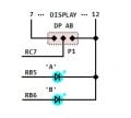
The <SET> switch is used to toggle between "set" and "run" modes. Press <SET> to enter "set" mode and the "hours" display group will flash at a 2-Hz rate. While in "set" mode the <Rt> arrow key is used to toggle between the "hours" and the "minutes" display groups and the <Up> and <Dn> arrow switches are used to increment (+) or decrement (-) the value of the current flashing display group. The "hours" display group will rollover from 23 to 0 (+) or 0 to 23 (-) and the "minutes" display group will rollover from 59 to 0 (+) or from 0 to 59 (-). The <Up> and <Dn> arrow switches will repeat when held down. Press <SET> again to exit "set" mode and enter "run" mode (display stops flashing). While in "run" mode, the <Up> arrow, the <Dn> arrow, and the <Rt> arrow switches are disabled. Those switches are still sampled and debounced in the interrupt service routine and you'll still hear a "new press" beep when you press one of them, but they're ignored and cleared by the logic in the program.
Observations
This is the first time I've used a 32768 Hz crystal and so far it seems reasonably accurate, gaining just under one second per day, which I believe is within the 30 ppm crystal spec. I suspect this could be improved by grounding the crystal case and trying slightly different capacitor values (or a ceramic trimmer capacitor). Anyway, the accuracy is acceptable, for now, and I'm really looking forward to experimenting with some of the interesting PIC low power sleep modes that utilize the low power 32768 Hz crystal oscillator.
I hope someone finds this project useful.
Cheerful regards and happy Holidays, Mike
Hardware
The circuit was built on a Radio Shack prototype board (sku 276-149) with a plastic laminated paper silk-screen glued onto the component side of the board. I used 30 guage Kynar wire and point-to-point wiring on the copper side of the board.
The circuit does not include column/digit driver transistors and relies on the combined ~250 ohm RDS(ON) resistance of the PIC I/O pin high side and low side FET drivers for segment current limiting. The display is refreshed one segment at a time (1/32nd duty cycle) to provide even brightness across the entire display.
Parts List
Rich (BB code):
1 ea. PIC16F1828-I/P (DIP package)
1 ea. 0.1-uf (100nf) ceramic capacitor
2 ea. 22-pf ceramic capacitors
1 ea. 32768 Hz (12pf) watch crystal
1 ea. 10 kOhm, 1/8th watt carbon film resistor
4 ea. 1N914 or 1N4148 silicon switching diode
1 ea. Sparkfun COM-09483 Red Common Anode 4-Digit Display
4 ea. generic momentary contact switch
1 ea. Soberton GT111P Piezo Speaker

Misc. sockets, connectors, prototype circuit boardThe HEX file in the ZIP file attachment can be used directly with a PICKIT2, PICKIT3, or similar device programmer to program the PIC16F1828. The program source file is also included in the ZIP file attachment. The program was written using the free/lite version of BoostC from Sourceboost and it uses 339 of the 4096 words of program memory available in the 16F1828.
The program configures the 16F1828 to run from the internal oscillator at 8-MHz and the Timer 2 module is configured to generate 250-usec (500 cycle) periodic interrupts. The Timer 1 low power oscillator is enabled for the 32768 Hz crystal. The ISR (interrupt service routine) is responsible for refreshing one new segment of the display each interrupt and it also polls Timer 1 for one second time-base intervals for the RTC. All thirty two segments of the display are updated once every 8-msecs for a 125-Hz refresh rate (1/32nd duty cycle).
Operation
The <SET> switch is used to toggle between "set" and "run" modes. Press <SET> to enter "set" mode and the "hours" display group will flash at a 2-Hz rate. While in "set" mode the <Rt> arrow key is used to toggle between the "hours" and the "minutes" display groups and the <Up> and <Dn> arrow switches are used to increment (+) or decrement (-) the value of the current flashing display group. The "hours" display group will rollover from 23 to 0 (+) or 0 to 23 (-) and the "minutes" display group will rollover from 59 to 0 (+) or from 0 to 59 (-). The <Up> and <Dn> arrow switches will repeat when held down. Press <SET> again to exit "set" mode and enter "run" mode (display stops flashing). While in "run" mode, the <Up> arrow, the <Dn> arrow, and the <Rt> arrow switches are disabled. Those switches are still sampled and debounced in the interrupt service routine and you'll still hear a "new press" beep when you press one of them, but they're ignored and cleared by the logic in the program.
Observations
This is the first time I've used a 32768 Hz crystal and so far it seems reasonably accurate, gaining just under one second per day, which I believe is within the 30 ppm crystal spec. I suspect this could be improved by grounding the crystal case and trying slightly different capacitor values (or a ceramic trimmer capacitor). Anyway, the accuracy is acceptable, for now, and I'm really looking forward to experimenting with some of the interesting PIC low power sleep modes that utilize the low power 32768 Hz crystal oscillator.
I hope someone finds this project useful.
Cheerful regards and happy Holidays, Mike
Attachments
-
4.2 KB Views: 223
-
 63.9 KB Views: 161
 -
 182.2 KB Views: 177
 -
 61.5 KB Views: 179
Last edited: