 Facebook
 Google
 GitHub
 Linkedin
Introduction
Hello, my name is Itay Shtainberg and I want to share my first big electronic project with you: The Internet-of-Things Controlled Air conditioner.

This project makes the air conditioner in my house controlled from anywhere in the world, by running a web-server on an esp8266 wifi microcontroller and accessing it using any web browser.
In the webpage It is possible to do two simple things:
1. See If the air conditioner(from now I will refer to it as AC) is now on or off.
2. Turn the AC on or off in both heat or cool mode.
Building
step 1: reverse-engineering
Until now the AC was controlled from a small board which is located on the wall and has an IR reciver, some leds, piezo sounder and a button which can be optionally used if the Remote control is not working. All I need to do now is hack it and find where and how Im going to control it.

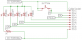
By just removing the cover of the board's box, I could see this interesting thing: free terminal headers! they must be connected to the circuit, and now I know it might be possible to control the AC with them. But I need to know the actual circuit going there. So I disconnected the board from the wall and by looking at the one layer traces I came up with this circuit:

(this schematic is not full and shows only the relevant parts for the project)
As you can see, there are 8 terminals which are coneected to different components:
O and Gd which are probably V+ and GND.
Gn, Bn, Bk which are connected to the cathodes of three LEDs - which also means the LED is turned on only when its cathode is LOW.
P which is connected to the button (!).
and the remaining are Y and R which are connected with some circuitary to the piezo and IR reciver-lets put those aside from now since we are not going to use them.
So to sum up there is an output/input for both the info LEDs and the button. This means I can probably:
Read the LEDs state and by that know if the AC is on or off.
Turn the AC on or off by sending pulses to the button input.
Then I connected the board back to the wall and started measuring with my multimeter.
Connecting the positive probe to O and negative to Gd shows 5V. this means: O is 5V+ and Gd is GND.
Then I checked the button. It showes that when pressed it is 5V, and 0V when not. this also proves I can send virtual "presses" by sending pulses to the P terminal.
The problem came when I checked the LEDs - their voltage just didn't make sense. so I came to AAC and got some help. It turns out the LEDs are powered with a pwm signal, which means that if the MCU read it in a single point of time - it can be read as both HIGH or LOW. but the solution will come later.
Then I checked the states of the LEDs in different modes, and it looks like this:

There is another "special" mode which happen when the AC was turned on from the remote (and not from the button). This mode goes between modes 1 and 2 (if the button is pressed while in this mode it turnes to mode 2) -
The LEDs in this mode: On/Off - On | heat - off | cool - off. I will call it the On,unknown mode because you cant know if it is turned on in heat or cool mode
Reverse engineering summary:
-The AC controlling board has an output of 5V - a good power source for an MCU
-The button on the board can be virtually pressed by sending 5V through It.
-The LEDs can be read from their terminals to see if the AC is off or on in cooling or heating modes, but they run on a PWM signal which is hard to read.
-There are 4 different modes for the AC, each shows as a different combination of the 3 LEDs.
After we know all of this, lets continue to the next step of the builld.
Step 2: The esp8266
In this part I will show the code I used and my esp8266 configuration.
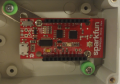
The module which I have chosen for esp8266 is the SparkFun Esp8266 Thing Dev Board which costs $15.95
There are some reasons for choosing it:
-More I/O lines than the minimalistic module.
-On-board voltage regulator which is good for the 5V output of the AC board (the esp8266 runs on 3.3V)
-On-board USB programmer which allows you to program the esp without external programmers.
-Little sized.
-A Good price for my opinion.

So I orderd the board from a local electronics/robotics store and got it.
Then I started expirementing with the arduino IDE esp8266 library and after learning the basics, I started writing the code for the project, which you can find in the attachments. The code is basically doing this:
-Connecting to wifi.
-Sets up a webserver.
-listens for incoming connections on root directory ("/").
-authenticates the user.
-the user can see the AC mode and press a button to change It.
-the esp will send x pulses to the button to change from one mode to other.
-the user will see a confirmation if the mode was succesfully changed.
(you might find this code "spaghetti-sh" and I can understand you. but refactoring it will be harder for me than writing it).
From here lets go to the most important part of the build.
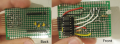
Step 3: External board, Opto-Couplers and RC filters
In the first step I encounterd two problems that might come in this step:
1. The LEDs that we want to read are powered with a PWM signal which is harder to read.
2. The button should recieve 5V in order to sign a click, but the esp8266 outputs only up to 3.3V
Firstly I will show you the design I came up with and then explain it:

In the thread I mentioned before, someone adviced me to use opto-couplers(or opto-isolators) to realy know if the LED's are on or off. I hadn't heared about it before but some search showed that it consist of a LED on one side, and a phototransistor on the other side. When the LED is on - the phototransistor will allow current to go trough it, and will block it if the LED is off.
Thats exactly what I need - To read if the LED is on or off. So as you can see the 3 upper opto-couplers are connected just like the original LED's on the board were connected. (I pulled the original LED's out of the board so the current for the opto-coupler will not be "stolen" by them).
The other part is the RC filter. It creates a "delay" of 0.1 seconds and by that eliminates the PWM pulses, so when a HIGH pulse arrive, It will stay HIGH at the input of the esp8266 for enough time before the capacitor discharges completely and another high pulse charges it. The resistor is also used as a pull-down for the input. Anyway Im still not sure how this works while the C and R are in parralel and not in the ordinary low-pass RC filter which is in series.

The fourth opto-coupler is used to control the button with 5V. This time the esp8266 is connected to the LED and the phototransistor is used as a switch that connect/disconnect 5V to the button.
The last part is the indicator LED which will light on when the AC is in any of the "on" modes. this is because I desoldered the old LED which were used to give visual feedback about the AC state. the "power" and "timer" LEDs however, are still connected because Im not reading them.
A connection I didn't mentioned yet is the power supply of the esp8266 which is coming from the old AC control board:

So we got everything set up, we can finish the project nicely with the last step:
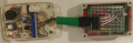
Step 4: Enclosure
This nice 80x60x35 (cm) project box was a good choose for the project. both the esp8266 and the external board sit perfectly inside, with the help of some metal "bridges" and screws. I created a hole for the 6 pins that comes out of the external board using a soldering Iron with a knife tip, and drilled another hole on the cover for the indicator LED. I cut 6 female to female wires to a shorter length, stripped them, and connected them to the terminal headers on one side, and to the 6 male pin header which are on the external board which I made.

And thats it. The project is finished and me and my family can control the air conditioner from anywhere in the world.
Parts list
Part | Quantity
LTV816C opto-isolator | X4
40x60 soldering board | X1
Plastic 80x60x35cm enclosure | X1
SparkFun esp8266 thing dev board | X1
1MΩ resistor | X3
200Ω resistor | X2
100nF capacitor | X3
Male pin headers | X~30
Female pin headers | X20
Female to female jumper wires | X6
22AWG jumper wire | Longer than ~20cm
I hope you liked this project - if you have any questions/advise/comments - I'd like to hear them.
I will probably also make a short demonstaration video of the project soon.
P.S. - I'm 14 years old.
Hello, my name is Itay Shtainberg and I want to share my first big electronic project with you: The Internet-of-Things Controlled Air conditioner.
This project makes the air conditioner in my house controlled from anywhere in the world, by running a web-server on an esp8266 wifi microcontroller and accessing it using any web browser.
In the webpage It is possible to do two simple things:
1. See If the air conditioner(from now I will refer to it as AC) is now on or off.
2. Turn the AC on or off in both heat or cool mode.
Building
step 1: reverse-engineering
Until now the AC was controlled from a small board which is located on the wall and has an IR reciver, some leds, piezo sounder and a button which can be optionally used if the Remote control is not working. All I need to do now is hack it and find where and how Im going to control it.
By just removing the cover of the board's box, I could see this interesting thing: free terminal headers! they must be connected to the circuit, and now I know it might be possible to control the AC with them. But I need to know the actual circuit going there. So I disconnected the board from the wall and by looking at the one layer traces I came up with this circuit:
(this schematic is not full and shows only the relevant parts for the project)
As you can see, there are 8 terminals which are coneected to different components:
O and Gd which are probably V+ and GND.
Gn, Bn, Bk which are connected to the cathodes of three LEDs - which also means the LED is turned on only when its cathode is LOW.
P which is connected to the button (!).
and the remaining are Y and R which are connected with some circuitary to the piezo and IR reciver-lets put those aside from now since we are not going to use them.
So to sum up there is an output/input for both the info LEDs and the button. This means I can probably:
Read the LEDs state and by that know if the AC is on or off.
Turn the AC on or off by sending pulses to the button input.
Then I connected the board back to the wall and started measuring with my multimeter.
Connecting the positive probe to O and negative to Gd shows 5V. this means: O is 5V+ and Gd is GND.
Then I checked the button. It showes that when pressed it is 5V, and 0V when not. this also proves I can send virtual "presses" by sending pulses to the P terminal.
The problem came when I checked the LEDs - their voltage just didn't make sense. so I came to AAC and got some help. It turns out the LEDs are powered with a pwm signal, which means that if the MCU read it in a single point of time - it can be read as both HIGH or LOW. but the solution will come later.
Then I checked the states of the LEDs in different modes, and it looks like this:
There is another "special" mode which happen when the AC was turned on from the remote (and not from the button). This mode goes between modes 1 and 2 (if the button is pressed while in this mode it turnes to mode 2) -
The LEDs in this mode: On/Off - On | heat - off | cool - off. I will call it the On,unknown mode because you cant know if it is turned on in heat or cool mode
Reverse engineering summary:
-The AC controlling board has an output of 5V - a good power source for an MCU
-The button on the board can be virtually pressed by sending 5V through It.
-The LEDs can be read from their terminals to see if the AC is off or on in cooling or heating modes, but they run on a PWM signal which is hard to read.
-There are 4 different modes for the AC, each shows as a different combination of the 3 LEDs.
After we know all of this, lets continue to the next step of the builld.
Step 2: The esp8266
In this part I will show the code I used and my esp8266 configuration.
The module which I have chosen for esp8266 is the SparkFun Esp8266 Thing Dev Board which costs $15.95
There are some reasons for choosing it:
-More I/O lines than the minimalistic module.
-On-board voltage regulator which is good for the 5V output of the AC board (the esp8266 runs on 3.3V)
-On-board USB programmer which allows you to program the esp without external programmers.
-Little sized.
-A Good price for my opinion.
So I orderd the board from a local electronics/robotics store and got it.
Then I started expirementing with the arduino IDE esp8266 library and after learning the basics, I started writing the code for the project, which you can find in the attachments. The code is basically doing this:
-Connecting to wifi.
-Sets up a webserver.
-listens for incoming connections on root directory ("/").
-authenticates the user.
-the user can see the AC mode and press a button to change It.
-the esp will send x pulses to the button to change from one mode to other.
-the user will see a confirmation if the mode was succesfully changed.
(you might find this code "spaghetti-sh" and I can understand you. but refactoring it will be harder for me than writing it).
From here lets go to the most important part of the build.
Step 3: External board, Opto-Couplers and RC filters
In the first step I encounterd two problems that might come in this step:
1. The LEDs that we want to read are powered with a PWM signal which is harder to read.
2. The button should recieve 5V in order to sign a click, but the esp8266 outputs only up to 3.3V
Firstly I will show you the design I came up with and then explain it:
In the thread I mentioned before, someone adviced me to use opto-couplers(or opto-isolators) to realy know if the LED's are on or off. I hadn't heared about it before but some search showed that it consist of a LED on one side, and a phototransistor on the other side. When the LED is on - the phototransistor will allow current to go trough it, and will block it if the LED is off.
Thats exactly what I need - To read if the LED is on or off. So as you can see the 3 upper opto-couplers are connected just like the original LED's on the board were connected. (I pulled the original LED's out of the board so the current for the opto-coupler will not be "stolen" by them).
The other part is the RC filter. It creates a "delay" of 0.1 seconds and by that eliminates the PWM pulses, so when a HIGH pulse arrive, It will stay HIGH at the input of the esp8266 for enough time before the capacitor discharges completely and another high pulse charges it. The resistor is also used as a pull-down for the input. Anyway Im still not sure how this works while the C and R are in parralel and not in the ordinary low-pass RC filter which is in series.
The fourth opto-coupler is used to control the button with 5V. This time the esp8266 is connected to the LED and the phototransistor is used as a switch that connect/disconnect 5V to the button.
The last part is the indicator LED which will light on when the AC is in any of the "on" modes. this is because I desoldered the old LED which were used to give visual feedback about the AC state. the "power" and "timer" LEDs however, are still connected because Im not reading them.
A connection I didn't mentioned yet is the power supply of the esp8266 which is coming from the old AC control board:
So we got everything set up, we can finish the project nicely with the last step:
Step 4: Enclosure
This nice 80x60x35 (cm) project box was a good choose for the project. both the esp8266 and the external board sit perfectly inside, with the help of some metal "bridges" and screws. I created a hole for the 6 pins that comes out of the external board using a soldering Iron with a knife tip, and drilled another hole on the cover for the indicator LED. I cut 6 female to female wires to a shorter length, stripped them, and connected them to the terminal headers on one side, and to the 6 male pin header which are on the external board which I made.
And thats it. The project is finished and me and my family can control the air conditioner from anywhere in the world.
Parts list
Part | Quantity
LTV816C opto-isolator | X4
40x60 soldering board | X1
Plastic 80x60x35cm enclosure | X1
SparkFun esp8266 thing dev board | X1
1MΩ resistor | X3
200Ω resistor | X2
100nF capacitor | X3
Male pin headers | X~30
Female pin headers | X20
Female to female jumper wires | X6
22AWG jumper wire | Longer than ~20cm
I hope you liked this project - if you have any questions/advise/comments - I'd like to hear them.
I will probably also make a short demonstaration video of the project soon.
P.S. - I'm 14 years old.
Attachments
-
 651.8 KB Views: 155
 -
 427.6 KB Views: 155
 -
 21.5 KB Views: 158
 -
 76.6 KB Views: 157
 -
 4.1 KB Views: 154
 -
 27.8 KB Views: 156
 -
 540.8 KB Views: 156
 -
 1 MB Views: 158
 -
 910.9 KB Views: 154
 -
2.8 KB Views: 12


