Help with reading a signal with a microcontroller

Thread Starter

128ITSH

Joined Jul 20, 2017
101
Hello everyone,
I am working on a project that its goal is to control the air conditioner in my house from a web page.
This is achieved by connecting an esp8266 (I am using the sparkfun thing dev board) to the old board on the wall that "controls" my air conditioner.

upload_2017-9-2_17-51-32.png
The old contol board (I will explain later why I ejected two of the LED's)
This board works in a way that all of the componnents are connected to one of the wires inside the cable and to a terminal socket which allowes external connections - this terminal is how I will connect the esp8266 to the board.

The communication between the esp to the control board will be with 4 lines - one to control the button input, and three to "read" wheather one or more of the leds is on or off.
the problem Im facing is reading those leds - which I will explain now:
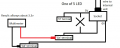
All of the LED's on this board are connected like in this schematic (each to a different terminal):


So as it looks, the LED is on when the line connected to its cathode is LOW, and off when its HIGH. but things get strange when I test this with a multimeter:
measuring the voltage between the LED terminal and ground will return around 3.3V either if the LED is on or off.
upload_2017-9-2_17-38-5.png
That means the esp8266 can't tell if the LED is on or off! however, I checked what happens if I eject the LED out of it place and the result is 0V if it is "off" and 0.3V if its "on", however, this small voltage is not readable by the esp which is operated on 3.3V.

Also if I check the voltage between the Vcc ('O' terminal) and an ejected LED terminal the result is 2.2V when LED is on and 0V when its off. but this is also too low to be considered a "1" by the esp, and also as far as I know a digital signal is compared to ground and not to Vcc.

So my question is: how can I Amplify this signal to 3.3V? I have looked to transistors but I don't understand all of these formulas.

I tried to be as clear as I can but I don't fully understand the problem myself, so if you can guide me through it I'll be very glad.
 

Attachments

philba

Joined Aug 17, 2017
959
Most LEDs in this type of application have a dropping resistor (either between the led and +V or gnd). There are two ways to energize that R+LED circuit - switch +V or switch GND. I'd guess it's the second one based on your readings. Try reading between the cathode of the LED and gnd. If the voltage is like 1.8-2.2V you are just measuring voltage drop across the LED and will need to find the dropping resistor and take the measure from the top of that. The LED and resistor may be switched.
led.png
If the voltage is too high, you might need to use a voltage divider to get it down to something that won't fry your ESP
 

Thread Starter

128ITSH

Joined Jul 20, 2017
101
Most LEDs in this type of application have a dropping resistor (either between the led and +V or gnd). There are two ways to energize that R+LED circuit - switch +V or switch GND. I'd guess it's the second one based on your readings. Try reading between the cathode of the LED and gnd. If the voltage is like 1.8-2.2V you are just measuring voltage drop across the LED and will need to find the dropping resistor and take the measure from the top of that. The LED and resistor may be switched.
View attachment 134224
If the voltage is too high, you might need to use a voltage divider to get it down to something that won't fry your ESP
Thank you very much for your help, but my problem is:
1. I don't have access to the top of this resistor (it's probably inside the internal unit).
2. My multimeter readings are strange and its hard for me to understand, but ill do more measures and come back with axact values tommorow.

by the way, what is the name of the software you use to draw these schematics?
 

philba

Joined Aug 17, 2017
959
unscrew the screws that hold the PCB. that will give you access to the back.

the .3V you read could the saturation voltage of what ever transistor (probably NPN bipolar) is driving the LED.

By the way, I don't understand what you mean by "ejected".

eagle PCB software.
 

Thread Starter

128ITSH

Joined Jul 20, 2017
101
unscrew the screws that hold the PCB. that will give you access to the back.

the .3V you read could the saturation voltage of what ever transistor (probably NPN bipolar) is driving the LED.

By the way, I don't understand what you mean by "ejected".

eagle PCB software.
1. I have already done this, and there is no resistor that connects to the LED on this board.
2. By "ejected" I mean that I pulled the LED out of the circuit with a soldering Iron to see if it will helps me read the signals better.

These are the values im reading with my multimeter:

upload_2017-9-4_16-32-51.png

And this is exactly how the LED circuit works (the part of it which is on the board,since the LED line is going to the internal unit):
upload_2017-9-4_16-35-44.png

Thank you again for the guidence, I hope that you can help me with understanding all of these values.
 

be80be

Joined Jul 5, 2008
2,394
What do you think your going to find the power led just comes on with power to show you have power.
Be more helpful if you posted the part number on the back its part of a remote looks like a AC
remote box i use some on ac in motel rooms years back that was like this.
IR Remote Control Extender
 

Thread Starter

128ITSH

Joined Jul 20, 2017
101
What do you think your going to find the power led just comes on with power to show you have power.
Be more helpful if you posted the part number on the back its part of a remote looks like a AC
remote box i use some on ac in motel rooms years back that was like this.
IR Remote Control Extender
1. The LED I'm trying to read is not the power LED but 3 of the LEDs: On/Off LED (indicates if the AC works or not), Cool LED, and Heat LED.
2. I have already checked the part number and there is no schematic/info online.
 

Thread Starter

128ITSH

Joined Jul 20, 2017
101
The leds got nothing to do with making the AC come on or the Heat the black box IR does that
I know it and I already said, I'm Trying to read if the LED is on or off to check the state of the AC and show it on a webserver, not changing It. I rather do it by sending signals to the button that is on the board, which I don't have problem with. please read my earlier posts about it.
 

spinnaker

Joined Oct 29, 2009
7,830
I know it and I already said, I'm Trying to read if the LED is on or off to check the state of the AC and show it on a webserver, not changing It. I rather do it by sending signals to the button that is on the board, which I don't have problem with. please read my earlier posts about it.

What is turning the +5V on and off?

You probably should have a current limiting resistor between the +5 and the LED. Connect a binary input from your MCU between the resistor and the LED.
 

Thread Starter

128ITSH

Joined Jul 20, 2017
101
What is turning the +5V on and off?

You probably should have a current limiting resistor between the +5 and the LED. Connect a binary input from your MCU between the resistor and the LED.
1. The +5V is not turning on and off, but stays on, the LED line on the cathode is the one that changes state - I need help with reading this change.
2. In the seen part of the circuit (the other part is in the internal AC unit probably) There is no resistor.

To clarify the way the LED's are connected:
upload_2017-9-4_19-5-55.png

by the way, by binary input, do you mean a digital input or analog?
 

spinnaker

Joined Oct 29, 2009
7,830
1. The +5V is not turning on and off, but stays on, the LED line on the cathode is the one that changes state - I need help with reading this change.
2. In the seen part of the circuit (the other part is in the internal AC unit probably) There is no resistor.

To clarify the way the LED's are connected:
View attachment 134304

by the way, by binary input, do you mean a digital input or analog?

What is turning on LED1_Line etc? Your mcu or another device?

binary = digital.
 

Thread Starter

128ITSH

Joined Jul 20, 2017
101
What is turning on LED1_Line etc? Your mcu or another device?

binary = digital.
All of the schematic that I have drawn are present on the air conditioner external control board, which is connected to the internal unit through a cable that includes all of the lines.these lines are also connected to the external terminals as shown in the first picture.
My question is, how can my MCU tell if the LED is on or off, considering the voltages I measured? (those are in the table which I posted before).
 

be80be

Joined Jul 5, 2008
2,394
You can read the led state. I don't think it will load the line but the esp is not going to be your best bet cause it has only 1 adc pin and you have to load the led line using it. I would get a off board adc chip that's 5 volt and I2c and read it with the esp.
 

Thread Starter

128ITSH

Joined Jul 20, 2017
101
You can read the led state. I don't think it will load the line but the esp is not going to be your best bet cause it has only 1 adc pin and you have to load the led line using it. I would get a off board adc chip that's 5 volt and I2c and read it with the esp.
Reading it in with an ADC seams like an interesting idea. I'll give it a try.
 

be80be

Joined Jul 5, 2008
2,394
Good for you you But the op playing with the leds not going to turn on the AC it doesn't work that way and reading them and shorting them out not good. I no O got a box of this gunk from motel work I did just not one the same as his as far as shape and even the wire names go but it's a IR range extender. The ones I used the most also told if some one was moving in the room. This one doesn't do that.
 

Thread Starter

128ITSH

Joined Jul 20, 2017
101
Good for you you But the op playing with the leds not going to turn on the AC it doesn't work that way and reading them and shorting them out not good. I no O got a box of this gunk from motel work I did just not one the same as his as far as shape and even the wire names go but it's a IR range extender. The ones I used the most also told if some one was moving in the room. This one doesn't do that.
I have already said two times - I am not trying to turn the AC on or off, but to read if its on or off, and reading the LEDs will not short them.

There is no need for the complexity of ADC. a simple binary input should do. You might need to buffer the input.
How can I buffer the input according to the voltages I have measured in the table above? I guess a transistor would work but what will be the resistors values? The MCU input level is 3.3V.
 
Top