Facebook
 Google
 GitHub
 Linkedin
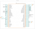
Hi all, I have recently built my own board for a project which uses a atmega 2560. Have had the pcb's made and have uploaded my code and got it all working but have noticed a few issues with the analog readings.
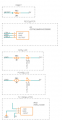
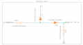
I have 10k pulldown resistors on some sensors to be able to show when the sensor wire is broken or been disconnected. They are pressure sensors and hall effect sensors so read 0.5v - 4.5v in normal operation so when disconnected i'd expect to see 0v.
Some of the sensors do indeed read 0v when disconnected but some read 1.1v and this has been confirmed with my multimeter the pin does indeed read 1.1v or thereabouts ( 1.05-1.09) on the multimeter).
Given this, I am assuming it has to be pcb related but nothing stands out to me.
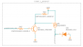
Given that i use 10k resistors for pulldowns or pullups on the whole board im assuming its something somewhere feeding a low voltage from 5v through a pull down to gnd pin through this 10k pulldown resistor but im not sure ive spent hours looking at my pcb and testing with a multimeter and cant work it out.

The reset pin is also pulled high to 5v with a 10k resistor so am wondering if this has something to do with it as they are the same resistor values not sure how they are linked internally on the atmega2560 though
Testing resistance between say Analog sensor 1 and sensor 2 inputs on the MCU gives a 20kohm resistance as expected ( connected to ground through 2 10k resistors ) so not sure if this is the issue either but i'm not sure where to go from here.
I can eliminate the pulldown resistors or even make them pull up resistors if I have to but id like to utilize it as will be easy to code when they are disconnected ( if the value is 0 or less than 0.5v when using pulldown or above 4.5 when using pull up) versus trying to work out when they are disconnected guess what will happen to the sensor values which could be hard based on vehicle environments which could float realistic values
Thanks,
Darcy
I have 10k pulldown resistors on some sensors to be able to show when the sensor wire is broken or been disconnected. They are pressure sensors and hall effect sensors so read 0.5v - 4.5v in normal operation so when disconnected i'd expect to see 0v.
Some of the sensors do indeed read 0v when disconnected but some read 1.1v and this has been confirmed with my multimeter the pin does indeed read 1.1v or thereabouts ( 1.05-1.09) on the multimeter).
Given this, I am assuming it has to be pcb related but nothing stands out to me.
Given that i use 10k resistors for pulldowns or pullups on the whole board im assuming its something somewhere feeding a low voltage from 5v through a pull down to gnd pin through this 10k pulldown resistor but im not sure ive spent hours looking at my pcb and testing with a multimeter and cant work it out.
The reset pin is also pulled high to 5v with a 10k resistor so am wondering if this has something to do with it as they are the same resistor values not sure how they are linked internally on the atmega2560 though
Testing resistance between say Analog sensor 1 and sensor 2 inputs on the MCU gives a 20kohm resistance as expected ( connected to ground through 2 10k resistors ) so not sure if this is the issue either but i'm not sure where to go from here.
I can eliminate the pulldown resistors or even make them pull up resistors if I have to but id like to utilize it as will be easy to code when they are disconnected ( if the value is 0 or less than 0.5v when using pulldown or above 4.5 when using pull up) versus trying to work out when they are disconnected guess what will happen to the sensor values which could be hard based on vehicle environments which could float realistic values
Thanks,
Darcy