Project Help

Thread Starter

Arsalan Raghib

Joined Mar 21, 2013
10
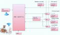
Hi everyone! I am new to PIC16F877A programming. I am making a project based on this controller. The project has just to sense current and make a decision to continue which supply. i need to know what is the current sensor? is there any ic in proteus software? can i compare current using pic comparator? The circuit diagram is given:
 

Attachments

djsfantasi

Joined Apr 11, 2010
9,156
  1. How much current are we talking about?
  2. Can the circuit, in which the current is monitored, be modified? I.e., do you want a non-invasive solution?
  3. Have you searched for "current sensor"?
 

Thread Starter

Arsalan Raghib

Joined Mar 21, 2013
10
I need small current upto 1 Ampere.
Yes the circuit can be modified and can be replaced by any solution.
Yes Sir i have studied about current sensor ACS712. But can it convert the current into voltage?
 

MikeML

Joined Oct 2, 2009
5,444
Looking at your pink diagram, I do not understand the project requirements. The way that your requirements are usually implemented is to use diode current steering; not current sensors..

It seems you need a AC powered DC power supply. That supply can also be configured to charge the battery. If the AC fails you want the three loads to automatically be powered from the battery. This is usually done doing steering diodes; not relays. Not even voltage sensing is required, since the switchover is totally automatic. It seems that the microprocessor is redundant, unless there are some other, unstated project requirements.

If the voltage(s) for the three loads are different, or need very precise regulation, then put individual voltage regulators downstream of a single set of steering diodes (where DC supply current is ORed with battery current).

What are the three required voltages? How accurate does the voltage have to be?
 
Last edited:

djsfantasi

Joined Apr 11, 2010
9,156
Did your search not return current sensor modules from Pololu or Sparkfun? The former ships worldwide. I've supplied a link to the Pololu sensors; they have a 5A version.

Will something like these modules help? They return a voltage linearly proportional to the current sensed.

Here is a description of a module.
This board is a simple carrier of Allegro’s ±5A ACS714 Hall effect-based linear current sensor, which offers a low-resistance (~1.2 mΩ) current path and electrical isolation up to 2.1 kV RMS. This version accepts a bidirectional current input with a magnitude up to 5 A and outputs a proportional analog voltage (185 mV/A) centered at 2.5 V with a typical error of ±1.5%. It operates from 4.5 V to 5.5 V and is intended for use in 5 V systems.​
 

Thread Starter

Arsalan Raghib

Joined Mar 21, 2013
10
Ok when i will connect the sensor output to the comparator of controller, will the controller detect the voltage for less than 1 ampere?
 

MikeML

Joined Oct 2, 2009
5,444
...when i ...connect the sensor output to the comparator of controller, will the controller detect the voltage for less than 1 ampere?
Review Ohms law! Voltage is measured in Volts. Current is measured in Amps.

What are you measuring?

Why are you measuring it?
 
Last edited:

djsfantasi

Joined Apr 11, 2010
9,156
Review Ohms law! Voltage is measured in Volts. Current is measured in Amps.
What are you measuring?
Why are you measuring it?
Mike, to clarify, the sensor I linked to outputs a voltage level proportional to the measured current. A current to voltage converter... Your other questions are excellent.

Ok when i will connect the sensor output to the comparator of controller, will the controller detect the voltage for less than 1 ampere?
The controller detects currents up to 5A; it will detect lower levels as well. Are you trying to detect a specific current level in a discrete manner, or what the current is in a continuous function? I ask, because in addition to the comparator, the PIC provides analog (output voltage) to digital conversion, up to 8 channels.
"The PIC16F877A features ... 2 Comparators, 8 channels of 10-bit Analog-to-Digital (A/D) converter..."​
The latter will give you a number for each level of the current sensor, in a continuous manner.
 

Thread Starter

Arsalan Raghib

Joined Mar 21, 2013
10
Sir actually i want to give control to the grid supply if solar energy is not able to drive the load. For this i think i will have to sense the current because all devices operate on 220 volts here. since P=IxV the voltage for each appliance will be same but current drawn will vary due to which the watt [power] of appliance vary. If there is any other solution please help me this is my final year project and i have no other source of help except the forums.
 

Thread Starter

Arsalan Raghib

Joined Mar 21, 2013
10
Mike, to clarify, the sensor I linked to outputs a voltage level proportional to the measured current. A current to voltage converter... Your other questions are excellent.


The controller detects currents up to 5A; it will detect lower levels as well. Are you trying to detect a specific current level in a discrete manner, or what the current is in a continuous function? I ask, because in addition to the comparator, the PIC provides analog (output voltage) to digital conversion, up to 8 channels.
"The PIC16F877A features ... 2 Comparators, 8 channels of 10-bit Analog-to-Digital (A/D) converter..."​
The latter will give you a number for each level of the current sensor, in a continuous manner.
The 2 comparators in PIC16F877A microcontroller compares the voltage. can it also compare the current?
 

Alec_t

Joined Sep 17, 2013
14,280
Pass the current through a sense resistor chosen such that the voltage V developed across the resistor is less than the PIC supply voltage. Then supply V to the comparator input.
 

ErnieM

Joined Apr 24, 2011
8,377
Pass the current through a sense resistor chosen such that the voltage V developed across the resistor is less than the PIC supply voltage. Then supply V to the comparator input.
This appears to be a very power limited controller. Sizing that resistor to directly feed the comparator will be needlessly wasteful of power.

Better to pick a small value resistor (so losses are minimal) and amplify the sense resistor voltage to something appropiate.

Also, putting the resistor in the negative lead, while a simple way to get a ground referenced sense voltage, does break the circuit ground. In the US this is a serious safety violation. The prefered method is to use a high side current sense chip (google that term, many manu make them) which keeps ground intact and will do the amplification for you.

I have no idea if Proteous handles these parts.
 
Top