 Facebook
 Google
 GitHub
 Linkedin
I am working on a simple traffic light system that changes lights dynamically depending on the presence of traffic via a load cell which will be incorporated later in my project. But right now I am having problems with clocking my chips. I am using a 74LS193 binary counter where each output by the chip represents a state that the signals are in. For example an output of 0000 is Green-Red and 0001 is Yellow-Red and 0010 is Red-Red etc. This design is dynamic because I am incorporating a Green(Hold) state which holds a green light indefinitely until a load cell picks up the presence of incoming traffic. Green and yellow lights do not stay lit for the same period of time, so my design implements a master clock that comes from a function generator and multiple edge triggers can activate depending on the output which are in junction through OR logic into the clock pin on my 74LS193. I have not yet implemented my load cell so my Green(Hold) state is simply skipped over by an automatic edge trigger on the occurrence of that output.
The Problem: My edge trigger refuses to trigger and my 74LS193 chip has a strange behavior.
Right now I have four positive edge triggers which uses a 74LS08 (AND) and 74LS04(INVERT). Two for Green(Hold) for both directions of traffic, one for reset, and one for the clock coming from the function generator. My edge triggers are working except for my Green(Hold) edge triggers. It is not working because the output of the edge trigger is always an active high instead of sending a single pulse on the occurrence of that state or it is simply ignored, and these two cases depend on the value of the resistor I use. I am currently using 100 ohms resistors and 0.1uF capacitors for the Green(Hold) edge triggers. At 100 ohms the edge trigger is ignored and when I use higher values, 10k ohms and 1M ohms, the output from the 74LS193 simply freezes on the edge trigger output.
The second problem that I am having is from my 74LS193 chip. I am using an edge trigger on the signal from my function generator because I only want a single pulse otherwise if the function generator is actively high it will override any edge triggers that I have. I noticed that the ONLY resistor and capacitor values that work is 100 ohms and 1nF. If I increase or decrease the resistance or I change the capacitance in anyway, the output of the chip is erroneous. What I mean by an erroneous output is that the output is completely random and not comprehensible.
My attempt at troubleshooting:
I do not have a scope so I cannot see how the signal propagates through my circuit, so I placed an LED on the output of the edge trigger to see what happens at that output. What I find is that when the edge trigger is skipped the output of the 74LS193 is behaves correctly, but the LED blinks on the occurrence of the state that triggers the edge trigger. When the 74LS193 is not working because the output of the edge trigger is outputting a constant high the 74LS193 chip the LED at the edge trigger is always on for that output. When I probe the input pins on the 74LS08 chip the problem seems to be that the signal to the input pin that is coming from the 74LS04 and RC section of the edge trigger is outputting a voltage of 0.1V BUT across the resistor and on the input pin of the 74LS08 chip itself my multimeter is telling me that the voltage is around 1.1V. So the actual "triggering" part of the edge trigger is working but the AND gate continuously thinks that there is some floating voltage which is strange as my reset and clock edge triggers are wired the same way and does not behave like this.
I have tried playing around with the RC time constant by changing the value of the resistors (I only have a pack of 0.1uF caps and some random capacitors that I just happen to have). But all attempts to change the RC time constant is futile. Of course the time constant for the edge triggers must be greater than the RC time constant for the clock edge trigger which I took into account. I have tried changing chips, rewiring, and quadruple checking all of my connections so I am very positive that my problems are not coming from any kind of mechanical failure.
An attempt to fix the problem of my 74LS193 chip, I have tried swapping it out with a 74LS192 chip but I still get the same result. There is not much functional difference between the 192 and 193 but here is a link for their description. https://www.futurlec.com/74LS/74LS193.shtml
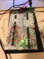
And finally I am using a 5V supply and a 0-5V function generator. Clock frequency does not affect my output but I am not using high frequencies anyways due to the nature of my desired output. I do not have any pull up or pull down resistors as they do not seem to have any affect on my output. Attached is an image of my current progress. Any resistors and capacitors are all for the purpose of edge triggering.
The Problem: My edge trigger refuses to trigger and my 74LS193 chip has a strange behavior.
Right now I have four positive edge triggers which uses a 74LS08 (AND) and 74LS04(INVERT). Two for Green(Hold) for both directions of traffic, one for reset, and one for the clock coming from the function generator. My edge triggers are working except for my Green(Hold) edge triggers. It is not working because the output of the edge trigger is always an active high instead of sending a single pulse on the occurrence of that state or it is simply ignored, and these two cases depend on the value of the resistor I use. I am currently using 100 ohms resistors and 0.1uF capacitors for the Green(Hold) edge triggers. At 100 ohms the edge trigger is ignored and when I use higher values, 10k ohms and 1M ohms, the output from the 74LS193 simply freezes on the edge trigger output.
The second problem that I am having is from my 74LS193 chip. I am using an edge trigger on the signal from my function generator because I only want a single pulse otherwise if the function generator is actively high it will override any edge triggers that I have. I noticed that the ONLY resistor and capacitor values that work is 100 ohms and 1nF. If I increase or decrease the resistance or I change the capacitance in anyway, the output of the chip is erroneous. What I mean by an erroneous output is that the output is completely random and not comprehensible.
My attempt at troubleshooting:
I do not have a scope so I cannot see how the signal propagates through my circuit, so I placed an LED on the output of the edge trigger to see what happens at that output. What I find is that when the edge trigger is skipped the output of the 74LS193 is behaves correctly, but the LED blinks on the occurrence of the state that triggers the edge trigger. When the 74LS193 is not working because the output of the edge trigger is outputting a constant high the 74LS193 chip the LED at the edge trigger is always on for that output. When I probe the input pins on the 74LS08 chip the problem seems to be that the signal to the input pin that is coming from the 74LS04 and RC section of the edge trigger is outputting a voltage of 0.1V BUT across the resistor and on the input pin of the 74LS08 chip itself my multimeter is telling me that the voltage is around 1.1V. So the actual "triggering" part of the edge trigger is working but the AND gate continuously thinks that there is some floating voltage which is strange as my reset and clock edge triggers are wired the same way and does not behave like this.
I have tried playing around with the RC time constant by changing the value of the resistors (I only have a pack of 0.1uF caps and some random capacitors that I just happen to have). But all attempts to change the RC time constant is futile. Of course the time constant for the edge triggers must be greater than the RC time constant for the clock edge trigger which I took into account. I have tried changing chips, rewiring, and quadruple checking all of my connections so I am very positive that my problems are not coming from any kind of mechanical failure.
An attempt to fix the problem of my 74LS193 chip, I have tried swapping it out with a 74LS192 chip but I still get the same result. There is not much functional difference between the 192 and 193 but here is a link for their description. https://www.futurlec.com/74LS/74LS193.shtml
And finally I am using a 5V supply and a 0-5V function generator. Clock frequency does not affect my output but I am not using high frequencies anyways due to the nature of my desired output. I do not have any pull up or pull down resistors as they do not seem to have any affect on my output. Attached is an image of my current progress. Any resistors and capacitors are all for the purpose of edge triggering.
Attachments
-
 223.6 KB Views: 11


