Facebook
 Google
 GitHub
 Linkedin
First of all, i dont know if this topic is located in the right place.
(and sorry for my "english")
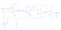
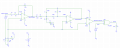
I'm doing a project and I have to use ultrasonic sensors. Right now I want to simulate the signal conditioning circuits. In this case, for starting, we have the emitter circuit (transmitter). Explained below:
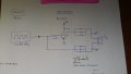
Starting from a square wave (clock) 5V, the circuit amplify this signal and send it to the ultrasonic sensor. Easy.
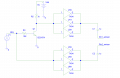
I'm starting to use Pspice / Schematics program and not dominated much it. My question is how I have to put the circuit to perform the simulation. In particular, how to add, or what I have to do with the component "to be the transmitter sensor" (located to the far right) . How to "close" the circuit for not leave floating components.
I attache the circuit I could more or less make in the program, but is incomplete.
(The sensor in question is MA40S4S)
Greetings and thanks in advance.
(and sorry for my "english")
I'm doing a project and I have to use ultrasonic sensors. Right now I want to simulate the signal conditioning circuits. In this case, for starting, we have the emitter circuit (transmitter). Explained below:
Starting from a square wave (clock) 5V, the circuit amplify this signal and send it to the ultrasonic sensor. Easy.
I'm starting to use Pspice / Schematics program and not dominated much it. My question is how I have to put the circuit to perform the simulation. In particular, how to add, or what I have to do with the component "to be the transmitter sensor" (located to the far right) . How to "close" the circuit for not leave floating components.
I attache the circuit I could more or less make in the program, but is incomplete.
(The sensor in question is MA40S4S)
Greetings and thanks in advance.
Attachments
-
 258.1 KB Views: 26
 -
 28.7 KB Views: 25