Facebook
 Google
 GitHub
 Linkedin
Dear all,
I am working on the design of an active band pass filter with a high quality factor, and I have encountered a problem with my circuit in which I solicit your help.
In the literature, it is said that when the quality factor of a filter is very large there is a possibility that the circuit oscillates, ie, the structure does not function as a filter but rather as an oscillator. Therefore, to check this, we must attack the structure by a square signal and see the nature of the output signal: is there always a square signal or we have oscillations.
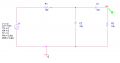
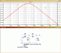
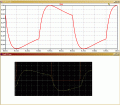
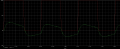
I tested this principle on my circuit but I do not find the good outcome. Therefore, I tried to check it on a simple RC circuit that works like a bandpass filter, but also I cannot find a square signal in the output, I have rather a distorted signal (attached figure).
Therefore, I would like to know if this method is correct. If so, why the RC bandpass filter not follow this principle? Moreover, is there another method to check the operation of a bandpass filter with a high quality factor?
Thanks for your help in advance.
I am working on the design of an active band pass filter with a high quality factor, and I have encountered a problem with my circuit in which I solicit your help.
In the literature, it is said that when the quality factor of a filter is very large there is a possibility that the circuit oscillates, ie, the structure does not function as a filter but rather as an oscillator. Therefore, to check this, we must attack the structure by a square signal and see the nature of the output signal: is there always a square signal or we have oscillations.
I tested this principle on my circuit but I do not find the good outcome. Therefore, I tried to check it on a simple RC circuit that works like a bandpass filter, but also I cannot find a square signal in the output, I have rather a distorted signal (attached figure).
Therefore, I would like to know if this method is correct. If so, why the RC bandpass filter not follow this principle? Moreover, is there another method to check the operation of a bandpass filter with a high quality factor?
Thanks for your help in advance.
Attachments
-
 41.1 KB Views: 44