Problem Square wave generator/Multivibrator astable with 741

Thread Starter

sunone

Joined Jan 11, 2011
10
Dear all!
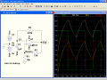
I am stuck with a very stupid problem, I am not capable of creating a square wave generator with an operational amplifier 741. The crazy thing is that I have done it many times.

I need a square wave with 50% duty cycle, where every wave lasts 0.5 seconds. I have done the math that matches this online script:
http://img101.imageshack.us/img101/9963/timer.jpg

As a dual power supply, I use 2 9v Batteries with the positive pole of one is connected to Vcc, the negative of the other t o -Vcc and the other poles to the Ground.

My oscilloscope doesn't see anything in the output, independently from the division. Nothing, flat... we lost him

My tester sees a constant tension of -1.7Volt... as if the multivibrator astable is saturated at that value.
Using a dual power supply of ±3volt, there is no change, exept the output of -0.3v, I tried other values of the capacitor as 1microFarad/25Volts a 1microFarad/50Volts, 1microFarad/63Volts, 1microFarad/100Volts and still nothing!!!

I changed the Operational amp. and still nothing.

This is a picture of the board
http://img46.imageshack.us/img46/661/dsc01563b.jpg

Using another board, the same... where the <snip> is the mistake ??!?!?!?:eek:
 
Last edited by a moderator:

edgetrigger

Joined Dec 19, 2010
133
Would you mind changing r2 to 10K, so 1/10th of output votage will be the reference.

rest of the ckt seems to be ok as long as you have connected the powersupply properly. Check the voltage on the oscilloscope in dc mode wrt to ground. You should get the trace switch to +vcc when measured at pin7 and -vcc when measured at +vcc. this is to ensure that the voltage is properly fed to opamp.

use +9/-9v setup as 741 works well above 5 volts supply.
 

SgtWookie

Joined Jul 17, 2007
22,230
You're using a polarized cap, and the voltage on it is going negative.

That is bad.

Disconnect the negative lead of the cap from your ground reference, and reconnect it to the -9v side of the batteries. Basically, just lift the negative cap lead out, and plug it in on the same row where your brown wire/-V and pin 4 of the 741 are connected. That should get you going, if the cap isn't destroyed.

The first cycle will have the timing off, but at least it won't fry your polarized capacitors.

You really should have 0.1uF and 1uF caps across the +v/-v supply pins of the 741.
 

SgtWookie

Joined Jul 17, 2007
22,230
Would you mind changing r2 to 10K, so 1/10th of output votage will be the reference.
That will change the timing of the circuit, and not fix the problem.

Our OP could change R1 to 10k and R2 to 12k; it would make the batteries last longer without upsetting the timing. As it is, there is a constant 3.5mA load on the output of the opamp, which will drain the batteries faster than necessary for no good reason.
 

Thread Starter

sunone

Joined Jan 11, 2011
10
awesome awesome awesome !!!!!!!!!!!! :):):):)
Changing the lead of the capacitor the problem is gone
You are my hero for today !

But know I have a series of questions :

1. Why is it working :) ? And before no ?

2. I am absolutely sure that I made it work in the settings I described in the past... why at that time, it worked... I could be I was using different values for the capacitor and the resistors.
 

bertus

Joined Apr 5, 2008
22,270
Hello,

A polarized capacitor can have a kind of diode effect.
This can make the charging of the capacitor to one polarity ok
and to the other polarity will have trouble.
(this is also the danger that the capacitor can get defective).
When connecting minus of the capacitor to the minus powersupply, this "diode effect" will not happen.

Bertus
 

SgtWookie

Joined Jul 17, 2007
22,230
awesome awesome awesome !!!!!!!!!!!! :):):):)
Changing the lead of the capacitor the problem is gone
You are my hero for today !
I'm glad that the fix was an easy one, and you didn't destroy your capacitor. :)

1. Why is it working :) ? And before no ?
As Bertus mentioned above, electrolytic capacitors must never have the polarity across them reversed. If this happens, the circuit may not work and the capacitor may be destroyed - if the current is sufficient, the capacitor may explode forcefully, raining alkaline aluminum confetti over your circuit.

I had you reference the negative side of the capacitor to the most negative voltage in the circuit (-9v; -v), so that the polarity across the capacitor is always correct.

2. I am absolutely sure that I made it work in the settings I described in the past... why at that time, it worked... I could be I was using different values for the capacitor and the resistors.
If you were using non-polarized capacitors, it would have worked correctly with one side of the capacitor connected to ground.

Also, please make the changes that I suggested above; replacing R1 and R2 with higher values - otherwise, your batteries will become exhausted much more quickly - and add at least a 0.1uF bypass capacitor across pins 4 (-v) and 7 (+v). Bypass capacitors are always required for IC's. Always read the datasheets to make sure that you are using the proper bypass capacitors.

See the "sticky" thread regarding bypass capacitors in the General Discussion Forum.
 

SgtWookie

Joined Jul 17, 2007
22,230
I've attached a simulation of your circuit with the proposed changes for R1 and R2.

Note the simulated O-scope plot on the right of the schematic.
V(out) shows the OUT signal varying from -8v to +8v.
V(C1,Vee) (white) shows the voltage on C1 when measured relative to Vee; note that it starts at 0v and after that is always positive.
V(c1) (yellow) shows the voltage on C1 relative to ground. Relative to ground, the signal goes from about -3.8v to +3.8v.
V(noninv) is the hysteresis feedback to the opamps' non-inverting input.
 

Attachments

tgu

Joined May 3, 2016
3
Hey

I am having a similar issue. Can you please submit a copy of the circuit as I cannot access the original that was posted.
 

Alec_t

Joined Sep 17, 2013
14,280
Vcc from one 9V battery goes to the +ve supply terminal (pin 7) of the 741. Vee from the other 9V battery goes to the -ve supply terminal (pin 4) of the 741.
BTW, the 741 is a lousy IC and a museum piece. There are much better (greater input/output voltage range, greater bandwidth and slew rate) opamps around nowadays.
 
Top