Presetting two 7 segments with a value using 4510 and 4511 drivers

Thread Starter

olivia_26_

Joined Sep 8, 2020
21
Hi,
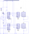
I am having a bit of difficulty completing the circuit for my A2 Coursework. I want to preload two seven segments so they count down from 13 but I am unsure how to do this. I am using a genie 20 chip and 2 sets of 4510 and 4511 drivers to control the 7 segments.
I have attached a pic of my circuit so far, could somebody tell me where I am going wrong?
circuit diagram example.PNG
 

Thread Starter

olivia_26_

Joined Sep 8, 2020
21
Hi Eric,

Thanks for your reply. I had a look at the diagram but I don't really understand it. I am still unsure of hot to pre-set a value.
 

ericgibbs

Joined Jan 29, 2010
18,766
hi,

That 1011 has Weighting of 8,4,2,1, so that is the Alpha Character for 'B'
You need two groups of 4 Bits
E


Or no 1101 sorry. is 8,4,2,1 == 13 = Alpha 'D'

Update:

Consider
0001 0011 .????
 
Last edited:

Thread Starter

olivia_26_

Joined Sep 8, 2020
21
Hi,

Thanks so much for your help. I don't want to be a pain but I am still unsure of how to programme the value. I asked my teacher but he said he didn't know and to look it up online. I haven't been able to find any relevant or helpful information which is why I started the thread here.
 

ericgibbs

Joined Jan 29, 2010
18,766
hi,
On your circuit diagram the PLoad is called LD.

You have to pulse the LD's pins Up and Down ONCE, when you power ON or you could add another push switch [ just like the Reset circuit]

Do you follow OK.?

I cannot help to too much as this homework.:)
E
 

Thread Starter

olivia_26_

Joined Sep 8, 2020
21
Hi,
Yes I follow that part, I can't add more ptms because the counter is supposed to start automatically so would I be able to wire the LD pin to +v instead of to ground and would that act as a pulse or do I need to physically pulse it in the flowchart?

I understand you can't help too much, I am trying to figure it out myself but we have just never been taught how to use 7 segments properly.
 

ericgibbs

Joined Jan 29, 2010
18,766
hi,
It has to be a Pulse.

Consider a simple Resistor/Capacitor connected across the +V supply and 0V, that would give a Pulse at Power On.
Post a image showing how you would connect it.

[Dont forget you must disconnect the existing 0V thats already connected to the LD's]

E
 

ericgibbs

Joined Jan 29, 2010
18,766
hi,
Woops.!
That will give Low going LD Pulse, then pull LD permanently High.!

also
The ENable must be wired permanently Low as in the original circuit.

Re think it.
E

BTW: footnote.
When designing a circuit you must consider how the user expects it to work.

On your initial circuit, at power On the 4510's count value can be in an indeterminate state, ie: 28 etc whatever.

The user has to press the Reset to Set the count and LCD to '00', BUT when you pulse the LD pins on the revised circuit, at power On it will display '13'. Which you can then count Down to '00' OR Less!!!!

To reload the '13' value you will have to power off the circuit, wait a couple of seconds, then power back On to reload the '13',, this a pain.

Consider if the Reset was automatic at power On and the 'old Reset' push switch now controlled the LD pins..

Operation would be power On, displays '00' , push switch loads PL '13'.

So the user after counting down to '00' presses the LD switch and reloads the '13' ,,, no Power Off/On required.
 

Thread Starter

olivia_26_

Joined Sep 8, 2020
21
Ok so I have put the EN pins to ground and I have also put the L1 and L2 pins for the units high and the L1 pin for the tens high as well. I don't think this is right though as I tested it and both 7 segments automatically went to 8.

The suggestions in your footnote make a lot of sense, I think I'll try and get the circuit working and then I'll sort out the reset.

Thanks,
Olivia
ciruit 3.PNG
 

Thread Starter

olivia_26_

Joined Sep 8, 2020
21
If its too complicated, do you think I should just use 1 seven segment and preload it to countdown from 9?
I really appreciate your help but I don't want to waste anymore of your time trying to explain it.
 

ericgibbs

Joined Jan 29, 2010
18,766
hi,
Look at this image note the positions of the R and C.
E

Update:
If you feel that you are learning, you are not wasting my time.

I am due to log off in a few minutes, but I should be around early in the morning.;)
 

Attachments

Top