Precision diode circuit design

Thread Starter

PeteHL

Joined Dec 17, 2014
562
This was published by National Semiconductor Application Note 31 February 1978, "Op Amp Circuit Collection".

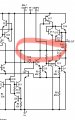
My question is what diode D2 does in the operation of the circuit. Also can I have a precision diode with a negative voltage output by reversing the orientations of the two diodes in the circuit?

Pins 1 and 8 are compensation terminals of the LM101 op amp. As I have very little understanding of the actual op amp circuit I don't have a clue as to how diode D2 alters operation of the circuit not including it.
 

Attachments

Thread Starter

PeteHL

Joined Dec 17, 2014
562
That circuit does not appear to be a precision diode circuit, since there is positive feedback from the output, through the diode, to the (+) input.
Thanks, Crutschow. Just now I fixed it. Sorry for not paying attention. The positions of the input terminals of the op amp in the original schematic and my drafting program are opposite.
 

schmitt trigger

Joined Jul 12, 2010
2,053
The LM101 is a quite unique opamp, where several internal nodes are brought out to the external world.
This app circuit uses these unique characteristics. If you find and post the internal circuit, we (together) can figure out what is actually going on.
 

Thread Starter

PeteHL

Joined Dec 17, 2014
562
The LM101 is a quite unique opamp, where several internal nodes are brought out to the external world.
This app circuit uses these unique characteristics. If you find and post the internal circuit, we (together) can figure out what is actually going on.
LM101.png
LM101.png
 

Thread Starter

PeteHL

Joined Dec 17, 2014
562
Yes if you reverse the feedback diode D1, and add a negative voltage supply.
You likely then don't need D2.
Where would the negative voltage supply connect to the circuit? Also the op amp already has a negative supply voltage connected to pin 4 of the op amp. Sorry, but I don't understand this part of the configuration that you propose.
 

Thread Starter

PeteHL

Joined Dec 17, 2014
562
Hardware testing the circuit of my post #1 with -7VDC at the (+) input terminal, then diode D2 prevents the op amp from saturating and holds the output terminal pin 6 at -400mV, with respect to ground.
 

crutschow

Joined Mar 14, 2008
38,392
Where would the negative voltage supply connect to the circuit? Also the op amp already has a negative supply voltage connected to pin 4 of the op amp. Sorry, but I don't understand this part of the configuration that you propose.
Sorry, missed that it already had a negative voltage.
Just reverse both diodes, and it should then give a negative half-wave output.
 

ronsimpson

Joined Oct 7, 2019
4,660
No Diodes!
Years ago when R-R opamps were first introduced, I mad rectifiers using them. The output needs to be made with MOSFETs not junction transistors! Maybe you can see the outputs are a little sticky and take some time to get off of ground.
Here I am using a slow 1.5mhz amplifier. Choose an amp with R-R inputs and R-R outputs.
Blue is one output. Red is the other. Green is the input. 2Vpk 1khz.
1760630789000.png
Here is a picture with better colors.
1760631270892.png
 

Attachments

ronsimpson

Joined Oct 7, 2019
4,660
though the Vf glitch is about 90-120mV.
I think the glitch is about the time it takes for the amp to come off the rains, not the voltage. But I have not look at it in years. This op-amp is only good to 0.9 volts/microsecond. I think a 10V/uS amp might do a better job.
In this case I don't trust SPICE. We should see what a real part does.
 

MrAl

Joined Jun 17, 2014
13,680
Hi,

Yes one of the things about op amps is once they are taken out of the linear mode, they can take a rather long time to get back to linear.
One example is the LM358 which is pretty slow to recover due to the internal capacitor used for compensation.
 
Top