 Facebook
 Google
 GitHub
 Linkedin
I tried to make a small PCB layout using the following parts
1. Screw terminal 2 Pins
2. Screw terminal 2 Pins
3. Diode 4N1007
4. Capacitor
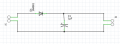
Schematic diagram: I made one schematic

PCB layout : I have converted schematic into the layout

It is just a small experiment and I need your opinion with my small example
Is it good design or I need it to modify for a better result?
If it's good then I wish to add more component's
Note : It is just an experiment for PCB designing
1. Screw terminal 2 Pins
2. Screw terminal 2 Pins
3. Diode 4N1007
4. Capacitor
Schematic diagram: I made one schematic
PCB layout : I have converted schematic into the layout
It is just a small experiment and I need your opinion with my small example
Is it good design or I need it to modify for a better result?
If it's good then I wish to add more component's
Note : It is just an experiment for PCB designing
Attachments
-
 9.9 KB Views: 2


