Practical implementation of an RLC circuit

Thread Starter

8dm7bz

Joined Jul 21, 2020
199
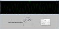
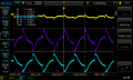
Alright so I set up the scopes and measured 3 different points. I attached the measurements and the simulation of those 3 points aswell. I would say it got a little better, but still not very good (maybe that's because it's not an accurate differential probe?).

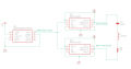
a little helper: the colours in the simulation correspond as follows:
green - across capacitor
yellow - across coil
red - across resistor
 

Attachments

Thread Starter

8dm7bz

Joined Jul 21, 2020
199
I thought a little more about how to get whats wrong. I came up with a simpler setup which produces the same problem. I can measure it with a single ended probe, and use no bipolar drive. I attached everything.

I think it's easier to test and think about the circuit as opposed to the original one.
 

Attachments

Thread Starter

8dm7bz

Joined Jul 21, 2020
199
Is it possible that the output impedance of the MCP1402 is too high to drive a 20ohms load at resonance (according to here it is about 12ohms)? I think you mentioned this already. What could be done about that ? A lower output impedance mosfet driver or maybe a 10V high current opamp ?

-8
 
Last edited:

Thread Starter

8dm7bz

Joined Jul 21, 2020
199
Alright so based on another thread I changed my mosfet drivers to the MCP14A1201 (Inverting) and the MCP14A1202 (Non-Inverting). The output resistance is about 0.9 ohms (typical) to 1.5 ohms (maximum). Another thing I changed was, I put a 47nF and a 470nF capacitor in series, resulting in a approximately 42nF cap. I attached the circuit.

I made an accompanying simulation and measured a few thing to compare it to reality. The waveform with the load attached gets pretty close to reality (simulation attached).

The problem is that I don't get the expected voltage across my capacitor, inductor, or resistor. The real measured waveform is always approximately half the simulated one. Any more ideas why that could be ? That makes no sense to me...
 

Attachments

sparky 1

Joined Nov 3, 2018
756
Commendable effort, the basis of the cube; source is to emit B field
the sensor shown as a rectangular enclosed area having a conductor.

Just a few parts really. The sensor with a led circuit can be calibrated.
 
Last edited:

Thread Starter

8dm7bz

Joined Jul 21, 2020
199
A video about electromagnetic induction and a demo of what I'm trying to reproduce. Could you elaborate on how this is relevant for this thread ? I don't quite understand. Apologies!
 

MrAl

Joined Jun 17, 2014
11,389
Hello,
I want to implement an RLC circuit with a 1.49mH coil (https://www.grupopremo.com/3dcc28-3...tions-395x395x386mm-/1982-3dcc28-a-0150j.html I used the x-winding). I used a 47nF cap and a 20 ohms resistor. I added 3 ohms to the 20 ohms because that is the DC resistance of the coil.
Now, the green sine wave in the simulation is the voltage across the capacitor. But as you can see, in my measurement the voltage is much lower.
Why is that ?

thanks,
8
Hello there,

Did you check the coil at various AC drive currents?

Inductors are inherently non linear, and can be very non linear. That is because the permeability curve is very non linear with current. The permeability starts out low and gradually curves upward as the drive current increases. At some point it reaches the nominal rated value of the inductor. Before that though the inductance can be much lower than the stamped value. That will cause problems in many types of circuits especially tuned circuits.

For example, if the inductance is 5mH then the voltage across the cap might be say 30 volts, but if the current is low and the permeability is still low then the inductance can be only 0.5mH. As the current increases somewhat the inductance could climb quickly to 5mH, but before that it could be just 0.5mH which is 10 times lower than expected. That lower inductance would lead to a cap voltage of 5 times less than expected, or around 6 volts peak with an AC drive of 20kHz at 5v peak.

So see if you can make a few stand alone measurements of the inductor alone and see what it comes out to with low drive current and with a higher drive current.
The low current level could be around 30ma AC and the high drive current around 110ma AC 20kHz. These are sine wave tests.
 

Thread Starter

8dm7bz

Joined Jul 21, 2020
199
Yes I think you are onto something. But I think the problem is that I don't get nearly as much current as I should be.
I took out the coil and the capacitor and applied the dual drive to only the resistor, since the coil impedance and the capacitor impedance should cancel out anyways. The problem was that the square wave isn't stable across the resistor, so I can't get enough current.
 

sparky 1

Joined Nov 3, 2018
756
I posted two videos of the company's recommended demo and the basic Faraday's law concept for how it works.
In the demo video a close observation gives details about all the components coming together for final calibration.
The sensor box and led indicator are also relevant to the thread as a practical implementation.
Premo/AmphiTrack Demo kit might be willing to let you explore their product, To reproduce will most likely
end as a lawsuit however a less intrusive approach might include memorandum of intent developing a new product.
 
Last edited:
Top