Powering multiple sensors with same voltage/current requirement from single power supply

Thread Starter

knbryant89

Joined Jun 28, 2018
12
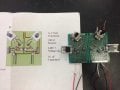
Hello! I have built multiple sensors which will be used to measure sap flux in a tree. I built power supply circuits to regulate two sensors at a time (parallel design - dual voltage regulator). Each circuit is designed to take in 12V from 12V battery and supply only ~2.5 Volts to each sensor. They work great when I hook each circuit individually to power source. However, I need to now connect multiple circuits to a single battery to deploy sensors outside into trees. Here are my specs:
Power supply = 12V deep cycle marine battery
Each sensor requires 0.2 Watts of power, ~0.115 amps and ~2.5 volts

I am new to electrical work so I don't want to wire the circuits together incorrectly and ruin all my circuits that I have spent weeks building. From reading different things, I think I should hook them in parallel rather than in series - is this correct?
If so, how do I go about doing that?
I have attached a picture of the circuit diagram next to a built circuit. Please excuse my ignorance as I am learning, but any help or advice is much appreciated!!
 

Attachments

Thread Starter

knbryant89

Joined Jun 28, 2018
12
Thank you! This may be a basic question, but do I connect all the 12V inputs to a single wire then connect that to battery positive? I can't imagine having each wire individually connected to the battery positive so how do I make it parallel with only one connection to battery positive?
 

dl324

Joined Mar 30, 2015
16,839
This may be a basic question, but do I connect all the 12V inputs to a single wire then connect that to battery positive? I can't imagine having each wire individually connected to the battery positive so how do I make it parallel with only one connection to battery positive?
You can do whatever is most convenient. Just make sure all wires can carry whatever current you run through them.
 

Thread Starter

knbryant89

Joined Jun 28, 2018
12
You can do whatever is most convenient. Just make sure all wires can carry whatever current you run through them.
Do you mean different wires are capable of carrying different current and some may not be able to handle the current? If so, how do I know which kind of wire is the right kind?
 

Thread Starter

knbryant89

Joined Jun 28, 2018
12
Then whatever wire you have is likely adequate.
How many sensors total?
Do you know the gauge of the wire you have?
I am using 20 G copper wire - is that adequate?
As for how many sensors - as many as I can power. There are 2 sensors for each dual regulator circuit so I would like to be able to hook up at least 6 circuits (12 sensors) to the same battery. How do I determine how many sensors is too many sensors?
 

crutschow

Joined Mar 14, 2008
34,280
How do I determine how many sensors is too many sensors?
It's when the voltage drop in the wire resistance from the supply to the sensor due to the sensor current is greater than the sensor can tolerate.

The wire voltage drop the total number of sensors times the sensor current times the wire resistance.

20AWG wire has a resistance of about 10.1mΩ/foot so you multiply the total sensor current times the total wire length (round trip) between the voltage supply and the sensor.
 

Thread Starter

knbryant89

Joined Jun 28, 2018
12
It's when the voltage drop in the wire resistance from the supply to the sensor due to the sensor current is greater than the sensor can tolerate.

The wire voltage drop the total number of sensors times the sensor current times the wire resistance.

20AWG wire has a resistance of about 10.1mΩ/foot so you multiply the total sensor current times the total wire length (round trip) between the voltage supply and the sensor.
Thank you so much for all your help! So, if I am understanding you correctly, this would be the equation: 10.1 * 2 feet of wire * (0.115 * # of sensors) ?
 

crutschow

Joined Mar 14, 2008
34,280
Yes expect that's 10.1mΩ or 0.0101Ω per foot, no 10.1Ω.

So the total length of wire from the power supply to all the sensors is only 2 feet?
 

Thread Starter

knbryant89

Joined Jun 28, 2018
12
Yes expect that's 10.1mΩ or 0.0101Ω per foot, no 10.1Ω.

So the total length of wire from the power supply to all the sensors is only 2 feet?
No, sorry, I was inserting a number for clarification of the equation. The farthest sensor will be about 2 ft from the power supply so "round trip" I guess 4 ft.
 

MaxHeadRoom

Joined Jul 18, 2013
28,617
If this is an external application for some period of time and subject to the elements, you can get direct burial landscape wiring.
I believe the smallest AWG is 14g.
Max.
 

Audioguru

Joined Dec 20, 2007
11,248
Why do you have so many LM317 circuits? Does each sensor need to have its voltage adjusted differently from the others?
Why does your circuit use an adjustment pot instead of a fixed resistor calculated to set the output at 2.5V?
One LM317 can provide an output of 1.5A and power up to 13 of those sensors if it is cooled with an attached heatsink. but your heatsinks are small.

What does a sap sensor do when there is sap on it? Squeal loudly? Send out a radio signal? Light an LED?
 

Thread Starter

knbryant89

Joined Jun 28, 2018
12
Why do you have so many LM317 circuits? Does each sensor need to have its voltage adjusted differently from the others?
Why does your circuit use an adjustment pot instead of a fixed resistor calculated to set the output at 2.5V?
One LM317 can provide an output of 1.5A and power up to 13 of those sensors if it is cooled with an attached heatsink. but your heatsinks are small.

What does a sap sensor do when there is sap on it? Squeal loudly? Send out a radio signal? Light an LED?
Yes each sensor has a slightly different resistance so each sensor needs to be regulated separately. Admittedly, I am a plant physiologist, not an engineer and am following a protocol/wiring diagram from a published methods paper, but unfortunately it isn't very clear about the details of connecting them all to the power supply. So, I apologize if my questions or diagram doesn't make sense and am open to any and all criticisms/advice. I came here because I am surrounded by plant experts, but really needed electrical/circuitry advice.

A sap flow sensor is composed of two 2 cm probes inserted in to a tree about 10-15 cm apart from each other. The upper probe is heated by a constant-current power supply (hence the circuits) and the lower probe is not heated, serving as a reference probe. The temperature difference between the two probes correlates to the flow rate of sap in the tree. When I am talking about sap, I am not referring to the sticky, sugary phloem sap that you are probably thinking of. I am instead referring to xylem sap - which is really just water, but called 'sap' because it contains trace amounts of amino acids, nutrients and hormones. My dissertation research focuses on the differential hydraulics of various tree species - specifically, do trees with different wood types exhibit different hydraulic responses to changes in atmospheric water status? So I am building these sensors and their associated circuits to essentially measure the flow rate of water through the tree over time. I hope that resolves your questions. So, no LED light or sound, instead I they will collect continuous data bout how water moves in trees - an active area of research in my field.
 

Thread Starter

knbryant89

Joined Jun 28, 2018
12
Also, the 2.5V was calculated based on the resistance of each sensor. Some are 2.3, 2.4, 2.6 - they all slightly vary but are around 2.5 because I constructed the sensors to be very close resistance values.
The original diagram didn't even call for heat sinks at all - they just used the LM 317s but after reading a bunch of electrical and circuitry boards it seemed pertinent to put a heat sink - plus the LM 317s were getting very hot.

I could make the sensors the exact same resistances if you think there is a way to connect more of them to one circuit. In fact, that would be great - I am very, very grateful for any direction on that!
 
Top