 Facebook
 Google
 GitHub
 Linkedin
Hi,
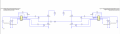
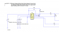
I'm doing the final part for my project using IR2110A for a power inverter. I've to add for my circuit a sawtooth wave generator and a reference such that I'll obtain a sinusoidal signal at the output.I don't know how to implement these for my circuit and I really appreciate your help
Thank you so much!
Attachments
-
 175.3 KB Views: 12
 -
 17.9 KB Views: 13


