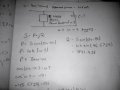
You make a mistake on the 3rd page. You assume that after adding the capacitor the apparent power does not change. The reason for adding the capacitor is to reduce the apparent power by shifting the pf closer to 1.0, i.e. reducing the current on the lines while still providing the same real power.
Also reactive power is in VARs and apparent power is in VA.
I can't see the last line on page 2, but the rest looks OK to me. You have the correct values for the network before the addition of the capacitor.
Page 3 is where you go astray.
After adding the capacitor, in parallel, it draws reactive power only. The real power to the total network remains the same, but the reactive and apparent power will change. The original load still sees the same voltage so it will still draw the original S,Q and P. But, the added capacitor will draw reactive current.
First determine the new total Q and the new S. You know the new pf and therefore the phase angle and you know P, so you can easily find Q and S.
I have to eat now, after dinner I will walk you through it. Not sure where you are going with pf=1, the new pf =0.9
If pf=0.9 and P = 7KW, then what are Q and S?
I have to eIa at now, after dinner I will walk you through it. Not sure where you are going with pf=1, the new pf =0.9
If pf=0.9 and P = 7KW, then what are Q and S?
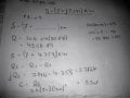
Iam sorry I was looking at another problem
If Pf=0.9 the P=s(.9)
p=10000*0.9=9000W (BUT The real power to the total network remains the same if P old = P new )
arccos(.9)=-25.84
And I get that you are saying that S is changed so 7k=s(.9)
s=7777.7VA
Q=S Sin(25.8)
so S=(7+3.299)k
S=S1-S2
S=(7-7)+(7.141j-3.31j)k
C=(3.831)k/(400)^2(2 π 60) C=63uF..?
when
power factor =.9
if I do tan(25.84)=Q/p Q=3.389 almost same ?
C=(3.831)k/(400)^2(2 π 60) C=63uF..? this eq. needs parenthesis to be clear
Almost correct
What is the frequency?
Define variables (s,S,S1,S2 ?) and don't skip intermediate steps, it's hard to follow, correct and is prone to mistakes. But I get the gist of what you did - looks good.
But your first paper says that the frequency is 50Hz, so which is it, 50Hz or 60Hz ???
Also, did you use 60Hz, because the paper says 50Hz ???
Did you get 63uf for the cap, using 60Hz or 50Hz ???
Obviously the frequency is very important, but the relationship between the frequency and the capacitor is linear:
C=K/f
with K a constant, so if the frequency is 60 to begin with and the capacitance is C1, then the required capacitance at 50Hz will be C2=C1*60/50.
There is also a short cut formula for C we can look at later that does not require knowing the inductance nor parallel resistance, just the apparent power, the two power factors, the voltage, and of course the frequency of operation.
I am posting the drawings again but more clear to read after enhancing the pictures, for the benefit of other readers.
 Facebook
 Google
 GitHub
 Linkedin
 75.8 KB Views: 17
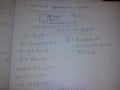 241.5 KB Views: 19
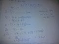 233.7 KB Views: 18