 Facebook
 Google
 GitHub
 Linkedin
Greetings from a long-term lurker. I want to humbly seek advice on a problem that's defeated my best attempts at solution.
History: I previously designed a controlled-resistance power supply for an associate. It had to deliver 6 V at 0.6 to 0.8 A. I split a 24 VDC supply with an LM675T to power the entire circuit. The device under test was a heated sensor with an attached platinum RTD. The bridge error adjusted the output to a second LM675T to keep the resistance constant. It has worked successfully for a year.
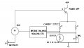
Now, he wants a circuit that will deliver 15-18 V at 0.6 to 1.0 A. The heater is platinum and also serves as the RTD. My first thought was 'scale everything up' and run it all from a split 48 V supply, but some important components, like instrument amps, don't seem to be available that will run on 48 V. Not to mention the heat sinking issues. So I'm shooting for a single-ended solution, run from a 24V, 2.5A supply. (See the attached figure.)
Experiments convinced me that the LM675 couldn't operate very close to the negative or positive rails without breaking into song (abt 80 kHz, even with compensation up the wazoo), even at gains of 20 or more. So it seems I have to default to another way to control the current, either a Darlington or a MOSFET.
My question: which would be the best solution in this case? I have little experience with MOSFETs in medium power applications. All suggestions welcome, please.
Thank you in advance,
Dangerous Bill
Restrictions:
- it needs to be DC; no PWM allowed, therefore, operation in the linear range
- one side of the sensor has to be grounded
History: I previously designed a controlled-resistance power supply for an associate. It had to deliver 6 V at 0.6 to 0.8 A. I split a 24 VDC supply with an LM675T to power the entire circuit. The device under test was a heated sensor with an attached platinum RTD. The bridge error adjusted the output to a second LM675T to keep the resistance constant. It has worked successfully for a year.
Now, he wants a circuit that will deliver 15-18 V at 0.6 to 1.0 A. The heater is platinum and also serves as the RTD. My first thought was 'scale everything up' and run it all from a split 48 V supply, but some important components, like instrument amps, don't seem to be available that will run on 48 V. Not to mention the heat sinking issues. So I'm shooting for a single-ended solution, run from a 24V, 2.5A supply. (See the attached figure.)
Experiments convinced me that the LM675 couldn't operate very close to the negative or positive rails without breaking into song (abt 80 kHz, even with compensation up the wazoo), even at gains of 20 or more. So it seems I have to default to another way to control the current, either a Darlington or a MOSFET.
My question: which would be the best solution in this case? I have little experience with MOSFETs in medium power applications. All suggestions welcome, please.
Thank you in advance,
Dangerous Bill
Restrictions:
- it needs to be DC; no PWM allowed, therefore, operation in the linear range
- one side of the sensor has to be grounded
Attachments
-
 17.8 KB Views: 28


