Potentiometer with min max settings

Thread Starter

Sambo1969

Joined Mar 29, 2018
6
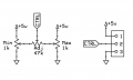
Hi, I am looking at modifying my foot pedal to a welding tig machine to include a min and max settings to the linear 10k pot currently in the pedal.

Would anyone have a circuit diagram required to connect another 2 pots for the min and max settings of the existing pot.

The footpedal controls the amps on the tig welding machine. Ranges from 5A to 200A.

Any assistance would be greatly appreciated.

Regards
Sam
 

crutschow

Joined Mar 14, 2008
34,282
You could put the added pots in series with each end of the original pot (perhaps 1kΩ to 5kΩ, depending upon how much you want to move the high and low settings).
The added pots would be configured as variable resistors (wiper connected to one end of the pot).
 

AlbertHall

Joined Jun 4, 2014
12,345
You could put the added pots in series with each end of the original pot (perhaps 1kΩ to 5kΩ, depending upon how much you want to move the high and low settings).
The added pots would be configured as variable resistors (wiper connected to one end of the pot).
That's assuming that the pot is wired as a potential divider.
It gets more complicated if it's wired as a rheostat.

How many wires are there from the pedal to the machine?
 

Thread Starter

Sambo1969

Joined Mar 29, 2018
6
That's assuming that the pot is wired as a potential divider.
It gets more complicated if it's wired as a rheostat.

How many wires are there from the pedal to the machine?
Hi Albert, 5 wires from the pedal to the machine. Two for the microswitch to start the gas solenoid and hf frequency ignition for the arc and three for the pot.

Regards
Sam
 

Thread Starter

Sambo1969

Joined Mar 29, 2018
6
I have added a circuit diagram
You could put the added pots in series with each end of the original pot (perhaps 1kΩ to 5kΩ, depending upon how much you want to move the high and low settings).
The added pots would be configured as variable resistors (wiper connected to one end of the pot).
Hi crutschow, thanks for your advice. I have a 10k pot(linear) for the pedal, and another 2 more 10k pots for the min max settings (linear). I have connected on the breadboard and machine starts at 100A and only the min pot works, but only moves 10A. I think it needs more components to work. I have attached a diagram for a similar pedal, but looks a bit more complicated. Rgds sam
 

Attachments

AlbertHall

Joined Jun 4, 2014
12,345
The Max and Min pots will interact so you will need to go back and forth between them.
Set the pedal to minimum and adjust the Min set pot.
Set the pedal to maximum and adjust the Max set pot.
Repeat these two steps until it is adjusted to your satisfaction.
 

AfdhalAtiffTan

Joined Nov 20, 2010
120
[crutschow]'s solution is fine, but, adjusting the min will affect the max and vice versa.
Assuming the bias and the input impedance are appropriate, you can try the following attached circuit.

The min and the max can be independently adjusted without affecting the other.
 

Attachments

dendad

Joined Feb 20, 2016
4,451
The min and the max can be independently adjusted without affecting the other.
Your circuit is a pretty good way to go I think. But a mod would be to add a resistor to the top of the Min pot and another to the bottom of the max pot to limit their ranges. otherwise, the setting pot could work in reverse if the Min is set above the Max setting.
 

AfdhalAtiffTan

Joined Nov 20, 2010
120
Your circuit is a pretty good way to go I think. But a mod would be to add a resistor to the top of the Min pot and another to the bottom of the max pot to limit their ranges. otherwise, the setting pot could work in reverse if the Min is set above the Max setting.
That is actually a very good idea!
 

crutschow

Joined Mar 14, 2008
34,282
The min and the max can be independently adjusted without affecting the other.
That's not strictly true.
The interaction may not be as large as with the pots in series, but one limit adjustment will still affect the other.
However the interaction may be small enough to not be a problem.

Using smaller resistance limit pots will reduce the interaction.
To get no interaction you would need to buffer the output of the limit pots with an op amp so that the voltage to the control pot has zero impedance.
 

Thread Starter

Sambo1969

Joined Mar 29, 2018
6
That's not strictly true.
The interaction may not be as large as with the pots in series, but one limit adjustment will still affect the other.
However the interaction may be small enough to not be a problem.

Using smaller resistance limit pots will reduce the interaction.
To get no interaction you would need to buffer the output of the limit pots with an op amp so that the voltage to the control pot has zero impedance.
Hi crutcshow, pots in series is the go. getting there with the min max settings. I can get the minimum to work well, which is a good help. At least not starting the welding at 5Amps (straight to say 60Amps). But by moving the other pot, it does change the range of amperage but strangely. What did you mean by op amp in your comments.

Regards
Sam
 

Attachments

Top