Potentiometer question

Thread Starter

archangeljess

Joined Dec 27, 2013
34
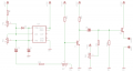
I found a schematic for fading LEDs. One of its components is a 10k 1/2 watt linear rotary potentiometer. When I inquired about this component, my local electronics store doesn't sell this one. They only have "ordinary" potentiometer. My question is, can I use any potentiometer instead of a linear rotary potentiometer?

Thanks
Jess
 

pwdixon

Joined Oct 11, 2012
488
The circuit will work but the brightness against pot position will be non-linear it rather depends what you are trying to do if you are just setting a light level by eye then you may be easily able to do what you want. It just means the intensity adjustment might be a bit sensitive on one end of the scale.
 

wayneh

Joined Sep 9, 2010
18,183
I found a schematic for fading LEDs.
If you share the schematic, we can offer many alternatives. Your local shop must surely have some linear pots, maybe at 5K or 50K? You can probably adjust your schematic to whatever parts are on hand.

You can also, in a bind, change the behavior of a pot by using additional external resistors.
 

Thread Starter

archangeljess

Joined Dec 27, 2013
34
By the way, since the schematic that I am using also uses a 555 timer IC, I am wondering why any 555 timer would emit too much heat. I have a police light flasher circuit which is working fine until i began experimenting on it. Any thoughts on what might have been the problem? Since I began working on electronics I have 3 fried 555 timers on my stash. Which demonstrates how stupid I am with circuits. But I am not giving up any time soon.

Thanks for the help.

Jess
 

MaxHeadRoom

Joined Jul 18, 2013
30,881
As it turns out, I'm gonna be shopping for "ordinary" pots.
In component jargon, these are described as 'Trimmer Potentiometers' , the circuit symbol also bears this out, in practice these are almost always 'Linear' types.
On the 555 heating, make sure you do not exceed the current rating of the output.
Max.
 

ScottWang

Joined Aug 23, 2012
7,509
The Pd of ne555 is 600mW, if the power is 12V, then the
I = W/V = 600mW/12V= 50mA, so the drawing current should be less than 50mA, if you want to use for some more then you can using a heatsink or adding a bjt or mosfet to drive the Load.
 

Thread Starter

archangeljess

Joined Dec 27, 2013
34
The Pd of ne555 is 600mW, if the power is 12V, then the
I = W/V = 600mW/12V= 50mA, so the drawing current should be less than 50mA, if you want to use for some more then you can using a heatsink or adding a bjt or mosfet to drive the Load.
Thanks for the information. May I refer you to another post so you could better understand what I mean.

http://forum.allaboutcircuits.com/showthread.php?p=686890

I am building a LED Police Flashing lights. I want to add more LEDs to the circuit and maybe a separate set of LEDs that flashes independent of what I already have made.

Thanks

Jess
 

ScottWang

Joined Aug 23, 2012
7,509
Thanks for the information. May I refer you to another post so you could better understand what I mean.

http://forum.allaboutcircuits.com/showthread.php?p=686890

I am building a LED Police Flashing lights. I want to add more LEDs to the circuit and maybe a separate set of LEDs that flashes independent of what I already have made.

Thanks

Jess
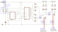
You can see the attached for reference.

The Vcc for the 555 is too high, usually we just using it up to +15V to the GND, but you used +18V, that is the rated voltage, it can't be work for long.

And the value of R2(1K), normally we using it with Vcc=5V, it is too less at here, when you offering the Vcc is >=12V then the R2 don't use 1K, it should be increasing more, we have to considering when the Vout(pin 3) is Low then the current will flowing through R2 to Vce of bjt inside of the Vout, The current will be I_R2 = (18V-Vce)/R2 = 17.8V/1K = 17.8mA,

The CD4017 can be offer -3.5mA, but that is at the +25℃, the calculation values of R3,R4 are 4.7K at +25℃, but we have to concerned the CD4017 may not keeping on that degree, so I reducing to 2.2K, the calculation value of R5, R6 close to 440Ω, but I don't want them to drawing too much current, and the 555 is working in a low frequency, so R5,R6 can be using a higher values.


Attachments

Thread Starter

archangeljess

Joined Dec 27, 2013
34
Thanks ScottWang. I appreciate your help. My power supply is not 9 volt as indicated in the schematic but 12 volts. How many LEDs will I be able to attach to this circuit?

What I just want to do is have 12 red LED, 12 blue LED and 12 white LED.
The blinking that I want to achieve is like this sequence:
blue flashes twice, red flashes twice...
white always flashing...

Would this be even possible?
What is the 820 in the resistors?

Thanks.

Jess
 
Last edited:

ScottWang

Joined Aug 23, 2012
7,509
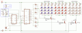
If you want to reducing the current of NE555 then you can following as what I changed.

The new circuit is using the darlington pairs to driving the LEDs, if you still want to using 2N3904 is ok, but you will need some more.

I'm calculating the current of LED, the Vce of TIP122 around 0.9~1.1V and I used 0.9V, the LED drawing current about 30mA, but the average current of blue and red LEDs <15mA, the white LEDs about 15mA, they will depends on the duty cycle of LED.

The Ic of 2N3904 are 200mA, if you want to use it, you just count it as I = 200mA/3 = 66.7mA, and calculate the numbers of LED and 2N3904.


Attachments

Last edited:

bertus

Joined Apr 5, 2008
23,027
Hello,

In post #15 there are no resistors on the bases of the transistors.
You will need them, otherwise the transistors and/or the chips will blow.

Bertus
 

Thread Starter

archangeljess

Joined Dec 27, 2013
34
Thanks for all your help. I'll be working on ScottWang's suggestions this friday. I'm sorry I didn't have much time replying to my thread. I've been busy last week.

I'll post some pictures or video if I have the time.

Thanks.


Jess
 

Metalmann

Joined Dec 8, 2012
703
"Since I began working on electronics I have 3 fried 555 timers on my stash."


Don't feel so bad, I've murdered quite a few more than that.:D
 

ScottWang

Joined Aug 23, 2012
7,509
"Since I began working on electronics I have 3 fried 555 timers on my stash."
Don't feel so bad, I've murdered quite a few more than that.:D
I just tried to use Triac circuit to dimmer the bulb which can't using that way, it was burned out and cost me about US$ 12.
 
Top