potentiometer {assisgnment}

Thread Starter

flextor63

Joined Nov 12, 2016
9
PLEASE HELP WITH ASSIGNMENT QUESTION.


PART A : Calculation Assignment


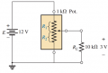
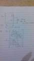
1. For the system below, a potentiometer of 1kΩ is used as a voltage divider. Later on a load which has a 10kΩ resistance is added.


. Determine the values of R1 and R2 to establish VRL = 3V when the load is applied.
 

Attachments

crutschow

Joined Mar 14, 2008
38,503
You have to show your best effort so we can help you arrive at the solution.
Do you understand Ohm's law and parallel and series resistor networks?
 

Thread Starter

flextor63

Joined Nov 12, 2016
9
I tried using thevenizing the circuit but I got stuck. without the load, I would be able to get the value of R1 and R2 as 750 ohms and 250 ohms respectively.
 

WBahn

Joined Mar 31, 2012
32,823
yes I perfectly understand ohms law and resistor networks perfectly
Obviously not very perfectly -- or even moderately well.

You've already been asked to show your work so that we can see what you are doing right and wrong. Saying that you "tried using thevenizing the circuit" but got stuck doesn't qualify as showing your work. If it did, then the best we could do after looking at your effort would be to say that you don't know what you are doing, which, of course, is obvious otherwise you wouldn't be here. But if you were to actually show HOW you "tried using thevenizing the circuit" we can see WHAT you did wrong and help you past it.
 

Thread Starter

flextor63

Joined Nov 12, 2016
9
Obviously not very perfectly -- or even moderately well.

You've already been asked to show your work so that we can see what you are doing right and wrong. Saying that you "tried using thevenizing the circuit" but got stuck doesn't qualify as showing your work. If it did, then the best we could do after looking at your effort would be to say that you don't know what you are doing, which, of course, is obvious otherwise you wouldn't be here. But if you were to actually show HOW you "tried using thevenizing the circuit" we can see WHAT you did wrong and help you past it.
should I begin to type my scribbles and rough work
 

WBahn

Joined Mar 31, 2012
32,823
should I begin to type my scribbles and rough work
Uh... yeah! Unless you really believe that we have some kind of crystal ball that let's us peer over your shoulder and remote view whatever you did.

Make your best attempt and post it. You can type it or take a picture of your work and post it (but try to keep the file sizes reasonable, as in a couple hundred kilobytes max).
 

bertus

Joined Apr 5, 2008
22,923
Hello,

You can use the GIMP for correcting the white balance and crop the image.
This is what I get as result for your image:

flector_calculations.jpg

Bertus
 

WBahn

Joined Mar 31, 2012
32,823
sorry my camera isn't very good
It's more than good enough. Thanks.

Other than being sloppy with your units ("1" and "10" are not resistances while "1 kΩ" and "10 kΩ" are) you have done fine (though I don't see any "thevenizing" going on anywhere).

Now just solve for x, since that IS the value of R2 and, once you have that, solve for R1 based on the constraint between R1 and R2.

If you don't get the right answer (which you can determine by just fixing R1 and R2 at the values you come up with and seeing if you get 3 V across the load with those values) the post your work from this point on and we can take a look.

It can also help to estimate some bounds on the answer. You came up with no-load values of R1 = 750 Ω and R2 = 250 Ω. Since 10 kΩ >> 1 kΩ, it is reasonable to expect that the actual needed values will be in this vicinity. We can further determine that since the addition of the load will cause the output voltage to drop, we need to increase the value of R2 to compensate. Thus the final value of R2 should be somewhat higher than 250 Ω, but not by much. For the parallel part, the load is ~40x the value of R2, so we can expect the needed change to be on the order of 1/40 of the value of R2, which would be 250 Ω / 40 or 6.25 Ω. So expect the actual value of R2 to be somewhere close to 256 Ω. We could look more closely to see if the value needs to be more or less than 256.25 Ω, but we've already narrowed the answer pretty tight. Just winging it, we can put up an approximate window of 50% of the 6 Ω and say that we expect the answer to be between 253 Ω and 259 Ω. This isn't an absolutely hard window, but if we get anything in that range it is probably correct while if we get anything outside of that range we probably need to look at it pretty skeptically.
 

Thread Starter

flextor63

Joined Nov 12, 2016
9
sorry I haven't replied earlier, I have been busy.

After solving for x I got a cubic equation: x^3+49x^2+360x-100=0

after solving I got values of x as : 0.26795180870133 , -39.91897940641037, -9.34897240229095.

the first value of x makes more sense. so my values for R1=732ohms, R2= 268ohms

and this gives me a value of Vout as 3.154volts.

don't know if this is correct but its close enough.

THANKS FOR YOUR HELP !!!!!!
 

crutschow

Joined Mar 14, 2008
38,503
don't know if this is correct but its close enough.
"Close enough" only works in government work. :rolleyes:
To check your solution, use your calculated values for the pot and see if you come up with 3V across the load.
Just make a Thevenin equivalent of the pot and use that to calculate the load voltage.
 

WBahn

Joined Mar 31, 2012
32,823
You should not be getting a cubic equation, so I suspect that the fact that one of your solutions is in the ballpark is pure coincidence. But without seeing your work that led to that cubic equation there isn't much I can do to help you find where you went wrong. Keep in mind that when you have multiple solutions to a problem that clearly has a single solution, all of the solutions but the correct one better be outright impossible (such as a negative resistance).
 

crutschow

Joined Mar 14, 2008
38,503
It might be easier to write the equations in terms of current rather than voltage.
You know the voltages across R1 and R2.
You know that the current through R1 must equal the current through R2 plus the load current.
Writing the equations for the current through R1 and R2 should give simpler equations to solve.
 
Last edited:

WBahn

Joined Mar 31, 2012
32,823
[QUOTE="flextor63, post: 1059965, member: 391697][/QUOTE]

You are making your life a lot more complicated than it needs to be. Instead of "cross multiply the bracket", simply multiply the numerator and denominator by (x + 10 kΩ). The way you are doing it masks the fact that, once you finish cross multiplying, the numerator and denominator have that shared factor. Go back and start from there and see what happens.
 
Top