Facebook
 Google
 GitHub
 Linkedin
Hello,
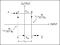
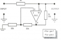
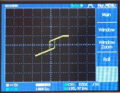
I am struggling to calculate the Schmitt Trigger for this circuit. I got 3.75V for when the switch occurs. Could someone please explain how to do it etc.
R1 is 18K and the input voltage is 5V
Thanks
I am struggling to calculate the Schmitt Trigger for this circuit. I got 3.75V for when the switch occurs. Could someone please explain how to do it etc.
R1 is 18K and the input voltage is 5V
Thanks
Attachments
-
 53.5 KB Views: 34
 -
 52.8 KB Views: 28
 -
 54.9 KB Views: 19