 Facebook
 Google
 GitHub
 Linkedin
I am sorry for posting such a basic question.
When I look at a power supply, I can only think of electrons flowing through a load.
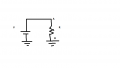
Please see the attached figure. What really flows through the resistor in this figure?
I believe positive terminal of voltage source cannot source electrons.
Does it mean that ground here can source electrons to node B of resistor?
Also, in the figure, is the upper terminal of resistor A is at higher potential or terminal B?
Regards,
When I look at a power supply, I can only think of electrons flowing through a load.
Please see the attached figure. What really flows through the resistor in this figure?
I believe positive terminal of voltage source cannot source electrons.
Does it mean that ground here can source electrons to node B of resistor?
Also, in the figure, is the upper terminal of resistor A is at higher potential or terminal B?
Regards,
Attachments
-
 9.8 KB Views: 14
")


