Pololu - step up/down voltage regulators - experience

Thread Starter

thor21

Joined Sep 29, 2024
435
@sghioto something weird is happening

when i connect 1x 0.5A device on the line,
than 2A device https://www.home-assistant.io/voice-pe/
and lastly 1A device - blink camera

all the time 1A device is connected/disconnected the https://www.home-assistant.io/voice-pe/ got restarted
even i cant measure any significant voltage drop during connection/disconnect of the other device.
Instead of 1A blink camera i tried also 1.8A amazon fire hd, same behavior.


And the most strange thing is that even no device is connected on the line, i set it to 5.05 V,
and when i connect google chrome tv hd - it start to boot but than shows the screen connect adapter. Even when i measured its original PSU - it is also 5.05V , 1.5V
I used some other charger 5V 2.5A and connected it - all worked fine.

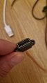
is it possible that these usb females are shitty? but all other devices even rated for 2A works ...


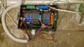
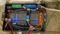
Lastly, the meanwell 60-5V which i use is producing some strange sound, its so quite but still something like "buzzing?"
And when connected https://www.home-assistant.io/voice-pe/ which has internal speaker; i can sense it on that device also.

So is it possible that faulty / low quality meanwell?


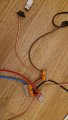
From the psu i do run 6mm2 cores, these go to WAGO and from wago short 0.5mm2 i think to usb female and then endpoint device is plugged.


thanks!
 

Attachments

Thread Starter

thor21

Joined Sep 29, 2024
435
Okay some observations, regarding the

1)
Google chromecase TV HD - it seems that all 4 cables has to be somewhere connected,
ie only + and ground connected wont boot the device properly even with an original PSU, when i connect to orig. PSU white, green it works... no idea why?

2)
regarding the https://www.home-assistant.io/voice-pe/ ; i used new usb cable so buzzing kind of disappear, but browning / rebooting is still there.

a)
When i connect on 6.5A psu 5.15V that Voice-pr device directly ; and then connect one more device 1A camera, no reboot.

b)
when i connect Voice - pe at the end of the 7m 6mm2 core; and attach 1A camera -> reboot.

c)
when i add one more 1.8A device ie ,
2A voice -pe
1A camera
1.8A - fire hd
the voltage at the end of the 7m drops from original 5.15V to 5.09V

Seems like a pretty mess :( with no way out.
 

Thread Starter

thor21

Joined Sep 29, 2024
435
what chatgpt says

Current: 5.5 A

  • Source voltage: 5.15 V
  • Cable length: 7 m one way → 14 m total
  • Conductor size: 6 mm²

ParameterValue
Voltage drop≈ 0.225 V
Load voltage≈ 4.93 V
Drop as % of supply≈ 4.4%


Interpretation

  • 4.93 V is safe for most 5 V digital devices
  • For USB-C / USB fast-charging electronics, 4.75–5.25 V is acceptable
  • Power-hungry SBCs (e.g., Raspberry Pi under load) may be borderline depending on brownout threshold


You said:


  • Source: 5.15 V
  • Load 1: Home Assistant Voice PE – ~2 A
  • Load 2: Camera – ~1 A
  • Total current: ≈3 A
  • Cable: 7 m each way, 6 mm² copper

We already know the round-trip resistance of that 7 m 6 mm² cable:

Rtotal≈0.0408 ΩR_{\text{total}} \approx 0.0408\ \OmegaRtotal≈0.0408 Ω
At 3 A total load:

Vdrop=I⋅R=3⋅0.0408≈0.12 VV_{\text{drop}} = I \cdot R = 3 \cdot 0.0408 \approx 0.12\text{ V}Vdrop=I⋅R=3⋅0.0408≈0.12 V
So at the end of the cable only:

5.15−0.12≈5.03 V5.15 - 0.12 \approx 5.03\text{ V}5.15−0.12≈5.03 V
That by itself is perfectly fine.
So the problem is probably not the 6 mm² / 7 m cable – that’s massive.


The problem is almost certainly in one (or more) of these:


  • PSU is not really happy at that current
  • Connectors / splitters / terminals add extra drop
  • Inrush current when the camera powers on makes a short dip → the voice-PE browns out


The weak spots are often:


  • DC jacks with tiny solder joints
  • Thin 0.25–0.5 mm² pigtails from PSU or splitter
  • Screw terminals that are not tightened well
  • Y-splitters / USB-splitters with tiny wires

Each connection might add only 0.05–0.1 Ω, but at 3 A:

V=I⋅R=3⋅0.1=0.3 VV = I \cdot R = 3 \cdot 0.1 = 0.3\text{ V}V=I⋅R=3⋅0.1=0.3 V
So you easily lose another 0.2–0.4 V just on connectors, which is enough to bring your 5.03 V (after big cable) down to 4.6–4.8 V at the device → reset.


Some cameras briefly pull way more than their “1 A” label at startup:


  • Capacitors charging
  • IR LEDs turning on
  • CPU boot spike

So even if continuous is ~1 A, there might be a short spike of 2–3 A extra, so total momentary current maybe 4–5 A.
 
Last edited:

Thread Starter

thor21

Joined Sep 29, 2024
435
regarding the chromecast issue


When you cut (interrupt) the white and green wires, you removed the USB data lines (D+ and D–).
Some devices (including Chromecast, Fire TV, and some SSD enclosures) do NOT turn on or allow full power draw unless the charger/cable signals through the data pins.


So even though only 5 V (red) and GND (black) are used for power, the Chromecast checks the data line condition to verify “proper charger”.

What the device expects

When connected to a charger, the USB cable normally has:


  • D+ and D– shorted together through a resistor
    → tells the device: this is a dedicated charging port, not a computer USB

OR


  • Specific voltage bias on D+ / D–
    (Samsung, Apple, QC, etc.)

Your original cable probably has the proper resistor → Chromecast accepts it.


When you cut D+ and D–:


  • Chromecast sees floating / open data pins
  • It thinks it’s connected to an unknown or unsafe power source
  • It limits power draw → triggers “use original charger” and may stop working


Simplest fix:
➡ Connect white (D–) and green (D+) together where you cut them.


Even better (USB-BC 1.2 compliance):
➡ Short D+ ↔ D– through a ~200 Ω – 1 kΩ resistor
(typically 56 kΩ per QC spec, but Chromecast is not strict — direct short usually works)


After that, the Chromecast will think it is a charger and will take full current.


Summary

ConditionResult
5V + GND only, data open❌ Chromecast refuses / limited power
5V + GND + D+ ↔ D– short✅ Works
5V + GND + proper charger signaling Best reliability
 

Thread Starter

thor21

Joined Sep 29, 2024
435
Regarding the
Google chrome hd tv - using resistor on data cable helped. Device works fine.

I can confirm all my usb Devices works fine on meanwell 5v suplly with 7m extension.


Only issue is voice pe, and i assume device is poorly designed.
Desperate what to do.
Chatgpt says add 4700uF or 10000uF capacitor.


Any idea?
 

Thread Starter

thor21

Joined Sep 29, 2024
435
regarding the voice-pe device, i will try to add
as chatgpt suggested, is that safe?

Add a capacitor close to the Voice PE input:


  • 470 µF – 1000 µF electrolytic
  • + 100 nF ceramic in parallel
 

Thread Starter

thor21

Joined Sep 29, 2024
435
so chatgpt also recco install protection and he proposed PTC or fuse and recco was PTC per each branch(endpoint device)


1)
main out from PSU
Slow-blow (T) 6.3 A 5x20mm

2)

Recommended PTC values for each device

Sure — here’s a condensed summary table of the PTC devices you need for your system, with suggested Iₕₒₗd and Iₜᵣᵢₚ values:


DeviceTypical CurrentPTC IₕₒₗdPTC Iₜᵣᵢₚ
Amazon Fire HD1.8 A2.0 A4.0 A
Chromecast1.5 A1.75 A3.5 A
Vero 4K2.0 A2.5 A5.0 A
Amazon Blink camera1.0 A1.2 A2.4 A
Z-Wave temperature sensor0.1 A0.3 A0.6 A

If you prefer just two PTC ratings to keep things simpler:


  • PTC Type A: Iₕₒₗd ~2.0 A / Iₜᵣᵢₚ ~4.0 A → use for Fire HD, Chromecast, Vero 4K, Blink.
  • PTC Type B: Iₕₒₗd ~0.3 A / Iₜᵣᵢₚ ~0.6 A → use for the Z-Wave sensor.


✅ Type A: for higher-load branches (~2 A hold / ~4 A trip)

  • 0ZCF0200AF2C PTC Resettable Fuse (2 A hold / 4 A trip): Example: “2 A hold / 4 A trip” rating. eBay+2Fusion+2
  • Littelfuse 2920L200/24DR PTC Resettable Fuse (2 A hold): SMD variant, good for ~2 A hold. Mouser Electronics+1

These are well-suited for your Fire HD, Chromecast, Vero 4K, Blink branches.


Type B: for low-load branch (~0.3 A hold / ~0.6 A trip)

  • 0ZCG0030FF2C (or equivalent) PTC Resettable Fuse 0.3 A hold / 0.6 A trip: Example from Bel-Fuse showing 0.3 A hold / 0.6 A trip. Fusion+1
  • MF‑R030‑0‑99 PTC Resettable Fuse 0.3 A hold / 0.6 A trip: Another solid variant. eBay UK+1

These are perfect for your Z-Wave temperature sensor branch.


Is that a good way to go or just model halucination?
Thanks!
 

sghioto

Joined Dec 31, 2017
8,634
Is that a good way to go or just model halucination?
Not a bad idea to have some kind of fuse if multiple 5 volt devices share the same feed.

Only issue is voice pe, and i assume device is poorly designed.
Desperate what to do. Chatgpt says add 4700uF or 10000uF capacitor.
Could try isolating the two devices using diodes and filter caps.
Crank the supply up 13 volts to compensate for the diode drop and line loss.
1763342059383.png
 

Thread Starter

thor21

Joined Sep 29, 2024
435
@sghioto
but are these numbers correct?
is it better to go for PTC instead of fuse (per branch)

Could try isolating the two devices using diodes and filter caps.
Crank the supply up 13 volts to compensate for the diode drop and line loss.
well but the PSU is 5.1V in that case, and i did typo chatgpt recco
Add a capacitor close to the Voice PE input:
  • 470 µF – 1000 µF electrolytic
  • + 100 nF ceramic in parallel
this should "protect from the micro speed drops?

there are currently 5 devices on 5V line
and 2 devices on 12V line,
i also ordered dc-dc polu brick from 12V to 5V 3A (on that line i want to attach) Voice PE device (the problematic one)
 

Thread Starter

thor21

Joined Sep 29, 2024
435
Yes only one voice pe,
You mean pololu brick?

Any point to add caps as ai suggested?

Also regarding the fuses can someone help here? Thx
 

sghioto

Joined Dec 31, 2017
8,634
Yes, the Polulo.
Don't see the need to add the caps if it's working OK without them.
I haven't any experience with those fuses.
Personally I would fuse each device with a standard type fuse of the proper value.
 

Thread Starter

thor21

Joined Sep 29, 2024
435
Will try polulo and let know.

I can use standard fuse, by a proper value... Is it value i provided above?

Not sure if there is some system to mount 5-6 fuses on 6 branches.
 

sghioto

Joined Dec 31, 2017
8,634
[QUOTE="thor21, post: 2010090, member: 1008099"
I can use standard fuse, by a proper value... Is it value i provided ?
[/QUOTE]
I suppose those values are OK.
 

Thread Starter

thor21

Joined Sep 29, 2024
435
these were proposed normal T fuses


DeviceSupply voltageTypical currentRecommended fuseNotes
Amazon Fire HD5 V1.8 AT 2.5 A / 250 V, 5×20 mmExtra headroom for battery charging inrush
Chromecast5 V1.5 AT 2.0 A / 250 V, 5×20 mmCovers peaks during boot/streaming
Vero 4K5 V2.0 AT 3.15 A / 250 V, 5×20 mmSafely above nominal, still trips on fault
Amazon Blink camera5 V1.0 AT 1.6 A / 250 V, 5×20 mmEnough margin for IR LED spikes
Z-Wave temp sensor5 V0.1 AT 0.25–0.5 A / 250 V, 5×20 mmVery small load; even 0.5 A is plenty
'

Per-device fuses (12 V side)

All fuses: 5×20 mm, T (time-lag / slow-blow), 250 V rated.


DeviceTypical currentRecommended fuseWhy
8-port switch0.5 AT 1.0 A~2× margin, handles startup spikes
Amazon Cube1.25 AT 1.6 ASlightly above nominal, safe for inrush
Lamp (12 V, 2 A)2.0 AT 2.5 A~1.25× nominal, good compromise


DeviceVoltageTypical currentRecommended fuseNotes
Voice-PE5 V~2 AT 3.15 A / 250 V, 5×20 mmBest balance of protection vs. startup peaks
 

Thread Starter

thor21

Joined Sep 29, 2024
435
i cant confirm that by adding 5v dc/dc before Voice-pe device there are no more brownouts,reboots.

Currently all six 5V devices are running fine and sharing one PSU.

thanks
 

Thread Starter

thor21

Joined Sep 29, 2024
435
Hello,
Thats how the box with psus looks like.

It also contains one relay from alarm system,
One card with 4 relays,
Resp psus.

Need to add fuse for each psu, or only the one that is shared between multiple devices?

The other end is in different room, 7m away. Once wall panel is done will share.

Also found out that i chose really small box for psus 12modules, so fault...

Also need to clean wagos...

Thx
 

Attachments

Top